17
Installation ow sensor (FS)
■
Mount ball valves up- and down-
stream of the ow sensor.
■
Consider the correct installation
point. Normally this is the return
(the colder pipe in heating sys-
tems). Please note the type plate
information.
■
Consider the correct ow direc-
tion. This is indicated by an arrow
on the side of the ow sensor.
■
Do not install at highest point of
piping to avoid air inside the ow
sensor.
■
Consider the dimensions of the
heat meter.
Installation of the ball valve
■
Mount ball valves up- and down-
stream of the meter.
■
Mount a ball valve with bore
M10x1 for the temperature sensor
installation.
■
For symmetrical temperature sen-
sor installation, mount a second
identical ball valve.
Mounting heat/cooling energy meter
■
Flush the system thoroughly
before installing the heat/cooling
energy meter.
■
Close valves and release pressure.
■
Dismount the existing ow sensor
/ tting.
■
Use only new and awless sealing
material, no hemp or similar!
Clean sealing surfaces and check
for damage.
■
Install the new ow sensor ac-
cording to the correct ow direc-
tion and installation position.
■
Turn heat computer to desired
reading position.
Installation of the temperature
sensors
■
The installation of the tempera-
ture sensors should be prefer-
ably symmetrical and as direct
installation.
■
Do not remove the temperatur
sensor if already mounted on
the ow sensor. This is also valid
for all the safety seals which are
mounted on the device as a
standard.
■
Sensors are colour-coded
(according to the model):
Red = Pipe with higher tempera-
ture level (supply in „Heating“
mode and return in „Cooling“
mode)
Blue = Pipe with lower tempera-
ture level (return in „Heating“
mode and supply in „Cooling“
mode)
■
The connecting cables may not be
buckled, extended or shortened!
■
The seal at the sensor installation
point on the ow sensor may not
be damaged.
■
Remove locking screw and seal
at the ball valve completely, if
existing.
■
Attach the O-ring to the installa-
tion aid (the 2nd O-ring is only a
spare O-ring). Using the installa-
tion aid, insert the O-ring into the
installation point according to
DIN EN 1434 with a slight circular
motion.
■
Using the other end of the instal-
lation aid bring the O-ring into the
correct position.
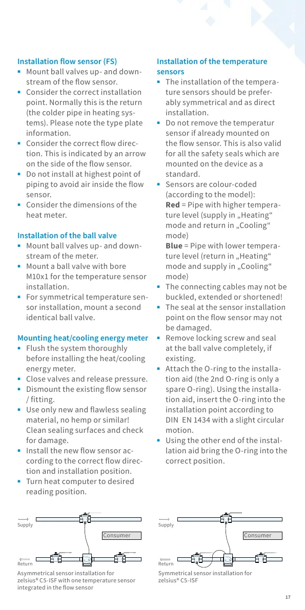
Asymmetrical sensor installation for
zelsius® C5-ISF with one temperature sensor
integrated in the ow sensor
Symmetrical sensor installation for
zelsius® C5-ISF
Supply
Return
Consumer
Supply
Return
Consumer
All manuals and user guides at all-guides.com
 Loading...