12000 Pecos Street, Suite 290, Westminster, CO 80234 | www.3xlogic.com | (877) 3XLOGIC
6.3 Part Names
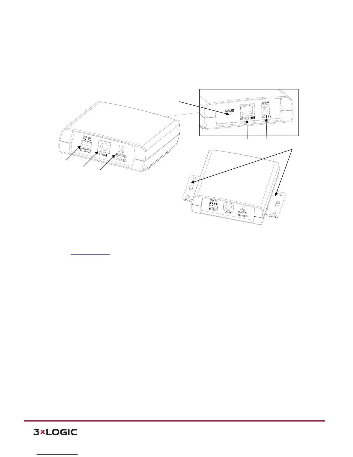
6.3.1 MAIN UNIT:
1). Terminal Connector: Connector for cable connection for digital input / output. Refer to Section 6.5:
Cable Connection for more details.
2). Camera Connector: Connector for camera unit
3). microSD/SDHC card slot: The camera supports up to 32GB. Class 4 and higher SD card is
recommended for HD recordings.
4). Reset button: This button will restart or reset to factory default settings.
5). LAN Connector: RJ45 LAN connector for 10/100 Base-T Ethernet (PoE supported)
6). Power Adaptor Connector: DC 12V power supply connection
7). Slide Plate: Built-in mounting bracket for main unit
 Loading...