Operation Manual / A150-M56/66/57/67 - A155-M..
11 Dismantling and fitting, cartridge concept / 11.8 Installing the cart-
ridge group
© Copyright 2021 ABB. All rights reserved. HZTL4032_EN Rev.Q January 2021
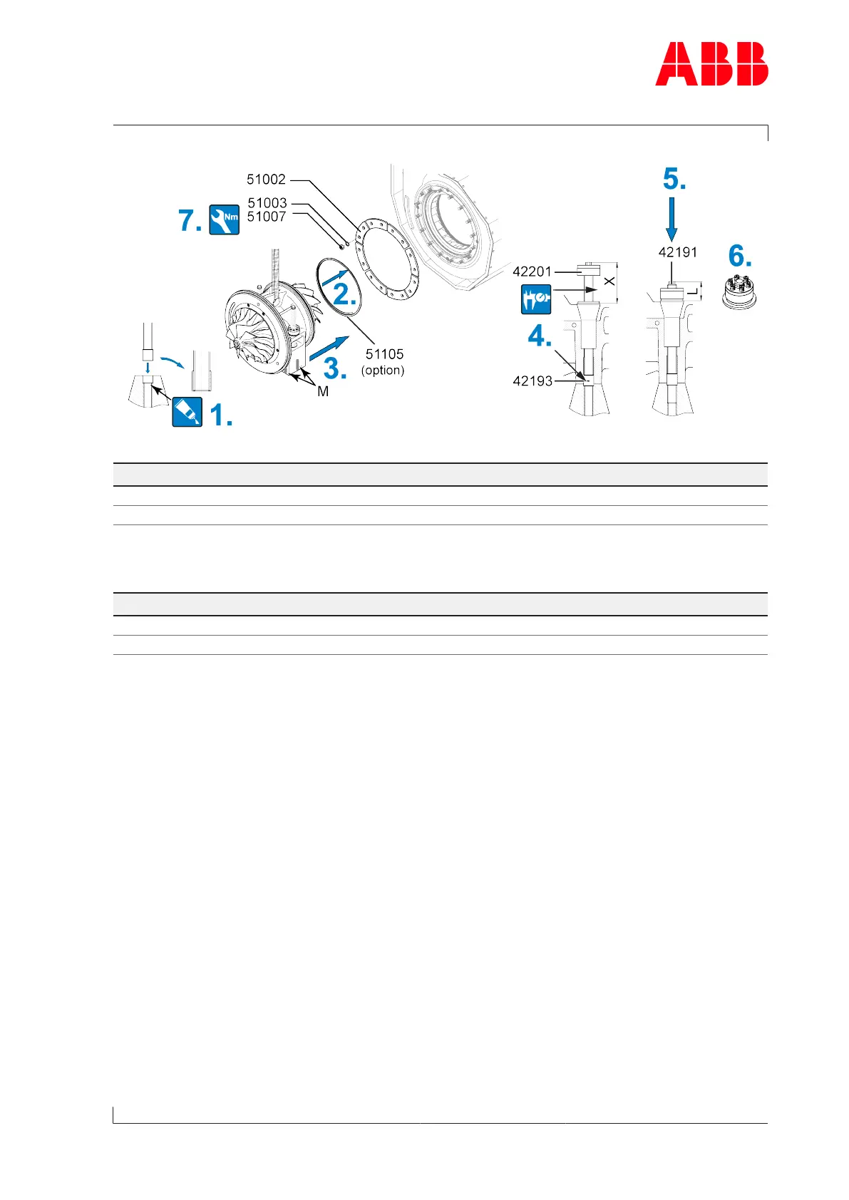
Fig.98: Installing the cartridge group 2
Product Value X [mm] Value L [mm]
A150-M 112 ±2 mm 52 ±2 mm
A155-M 144 ±2 mm 72 ±2 mm
Table59: Threaded rod, value X and L
Product Size Tightening torque [Nm]
A150-M M16 175
A155-M M16 175
Table60: Tightening torque (51007)
1. Lightly lubricate the hole in the bracket, into which the centering bush(42193) is inser-
ted, with screw grease.
2. If present: Insert the metal C-ring(51105).
3. Move the cartridge group into the turbine casing and align with the markings (M) made
on the bracket at the time of disassembly.
4. Screw clamping nut(42201) upwards to end of threaded rod and insert the centering
bush(42193) into the hole.
Check value X (if value X is not reached, the turbocharger must be re-aligned).
5. Screw in the threaded rod until value L is reached.
6. Tighten the pressure screws of the clamping nut (see Tightening pressure screws →37).
7. Secure fastening strips(51002) together with nuts(51007) and Verbus Ripp® wash-
ers(51003).
Page 143 / 194
 Loading...