M
Mustafa uzunFeb 27, 2025
Sürücüde oluşan 5133 arızası nedir
- MMUSTAFA UZUNFeb 27, 2025
BİZDE ÇALIŞMAKTA OLAN ABB 1000 TİPİ BİR SÜRÜCÜ VAR BU SÜRÜCÜDE BAZEN 5133 KOD ARIZASI VERİYOR BU KODUN ANLAMI NEDİR

 Loading...
Sürücüde oluşan 5133 arızası nedir
BİZDE ÇALIŞMAKTA OLAN ABB 1000 TİPİ BİR SÜRÜCÜ VAR BU SÜRÜCÜDE BAZEN 5133 KOD ARIZASI VERİYOR BU KODUN ANLAMI NEDİR
| Type | Medium Voltage AC Drive |
|---|---|
| Power Range | 315 kW to 5000 kW |
| Efficiency | Up to 98% |
| Output Voltage | 0 to Input Voltage |
| Cooling | Air or water-cooled |
| Enclosure | IP54 |
| Communication Protocols | Modbus, Profibus, Ethernet/IP |
The information in this manual is subject to change without notice.
This manual covers a standard drive and provides generic information on the drive.
The complete set of user documentation of a standard drive consists of this manual and supplementary documentation.
Lists terms and abbreviations to be familiar with when using this user manual.
Names believed to be trademarks of other companies and organizations.
Lists related documents such as maintenance schedules and technical data sheets.
Defines target audience and required qualifications for handling the drive.
Ensures personnel are trained and understand manual instructions and safety.
Specifies that the drive must be used only as specified and under stipulated conditions.
Customer's responsibility to ensure secure network connection and data protection.
Lists available ISO, EC conformity, and compliance standards for the drive.
Lists typical items included in the drive delivery package.
Explains identification of drive and accessories via type code on the rating label.
Read this material before working on or around the equipment.
Provides hazard level indicators (DANGER, WARNING, CAUTION) for injury prevention.
Uses NOTICE for practices not related to physical injury but causing equipment damage.
Describes safety labels affixed to components to alert personnel of potential hazards.
Provides instructions on minimizing hazards, before energizing, working on, and simultaneously working.
Series of actions for safe working on electrical installations, including risk assessment and isolation.
Identifies risks like electromagnetic fields, unintentional movement, touch voltages, and emissions.
Details the MCB's role as a protection device and its critical function in drive safety.
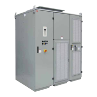
Describes the ACS1000 as a general-purpose frequency converter for induction motors.
Explains the block diagrams of ACS1000 with 12-pulse and 24-pulse rectifiers.
Details the two independent power supplies required for drive operation.
Introduces main components of the drive system like MCB, Transformer, Drive, and Motor.
Covers fan configurations, types, and operational principles for cooling the drive.
Describes the riveted and folded cabinet construction for strength and EMC protection.
Ensures safety by making all doors lockable, with electro-mechanical security for medium voltage compartments.
Provides optional arc fault protection in accordance with IEC 62477-2.
Optional heaters protect the cabinet from condensation by switching on when cooling is off.
Details hardware in the control compartment for control, monitoring, and protection functions.
Provides an overview of main hardware components of the control system and their interconnection.
Explains how analog and binary I/O signals connect to the control system via IOEC modules.
Identifies serial communication interfaces for data transfer to higher-level control systems.
Part of the control system for pulse encoder feedback used to control the motor.
The drive must only be handled by skilled and experienced personnel in unpacking and transporting.
Based on IEC 60721-3-2 classification for environmental conditions during transport.
Steps for removing packaging, checking for damages, and comparing delivery with purchase order.
Provides information on lifting and transporting the cabinet, referencing mechanical drawings.
Details minimum requirements for storage conditions, including conditions and storage time.
Instructs to dispose of materials and components according to local regulations.
All installation work must be carried out by qualified personnel according to site and local regulations.
Lists the steps involved in the installation process.
Provides notices on preventing component damage from foreign matter and dust.
Specifies floor conditions: support weight, evenness, non-flammable, smooth, non-abrasive.
Details drilling holes, checking alignment, and using anchor bolts for floor fixing.
Provides instructions for assembling and installing the air exhaust hood for drives with internal fans.
Guides the installation of the redundant fan unit, including removing lifting rails and covers.
Warns about hazardous voltage and emphasizes qualified personnel and proper procedures.
Includes wire and cable connections for power, ground, auxiliary, control, and serial communication cables.
Refers to specifications and guidelines for power, ground, auxiliary, and control cables.
Describes options for cable entry through roof or floor using EMC plates, sealing modules, or glands.
Details preparing cable entry, determining cable length, and splitting multi-core cables.
Explains preparing cable entry and connecting these types of cables.
Guides routing and connecting the power supply cable for the optional redundant fan.
Ensures entry plates are fastened and grommets fit tightly to prevent water entry.
Provides an overview of the commissioning process for the drive.
States that commissioning must be done by ABB-certified personnel only.
Information on commissioning procedure and start conditions can be obtained from ABB.
A checklist to prepare the drive and associated equipment for commissioning.
Requests qualified personnel for assistance during commissioning.
Describes signing the commissioning report and receiving settings as acceptance.
Checklist for verifying mechanical installation requirements before commissioning.
Checklist for verifying electrical installation requirements before commissioning.
Checks for MCB selection, connections, relay settings, and safety devices.
Checks for ground connection, transformer auxiliaries, and safety devices.
Checks for motor installation, alignment, ground connection, auxiliaries, and signals.
Ensures power cables are tested for insulation resistance within required limits.
Verifies availability of medium voltage and low voltage auxiliary power for start-up.
Checks spare parts availability, drive room air conditioning, and optional equipment.
Drive must be operated only by qualified and authorized personnel familiar with hazards.
Outlines the local operation of the drive, excluding remote control via PLC.
Specifies operating conditions according to IEC 60721-3-3 for stationary use.
Provides sound pressure levels for single and redundant fans.
Describes the operator panel functions for controlling the drive locally.
Lists messages for drive states like operation, stop, and fault conditions.
Details the sequence of events from NotReadyOn to Operation state.
Describes the sequence from Operation to NotReadyOn state upon receiving a stop command.
Outlines the sequence when an emergency-off command is initiated.
Recommends documents and provides a checklist for starting the drive locally.
Instructs to press the STOP key on the CDP control panel to stop the motor.
Explains the hard-wired emergency-off circuit and its operation.
Steps to unlatch the pushbutton and reset the safety relay to restart the drive.
Explains that panel messages and settings are typical examples for illustrating instructions.
Lists tasks performable with the panel: data entry, control, display, parameter adjustment.
Introduces modes like Identification, Actual Signals, Parameters, and Functions.
Informs about panel version and drive ID number when power is switched on.
Allows monitoring the drive by displaying three selectable actual values.
Allows entering parameter settings for drive configuration, organized in groups.
Used to set the display contrast by adjusting the contrast value.
Enables selecting control location (local or remote) via the LOC-REM key.
Covers starting, stopping, and setting direction of rotation from the CDP control panel.
Specifies that maintenance during warranty must be by ABB personnel.
Describes identification of devices, cables, and wires using labels and diagrams.
Explains how the CDP panel displays alarms and faults, and the meaning of error levels.
Steps to follow when a fault occurs, including saving data and contacting ABB service.
Provides instructions for removing the control panel, with safety precautions during operation.
Explains the meaning of LEDs and switches on AMC circuit board and IOEC modules.
Overview of maintenance tasks like visual checks, cleaning, and replacing components.