10 PREVENTIVE AND CORRECTIVE MAINTENANCE
3BHS799208 E01 REV E ACS5000 WATER-COOLED USER MANUAL 166/186
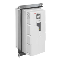
2. To remove the panel, proceed as illustrated.
IMPORTANT! When the CDP control panel has been removed during
operation, the drive can only be stopped by pressing the emergency-
off pushbutton.
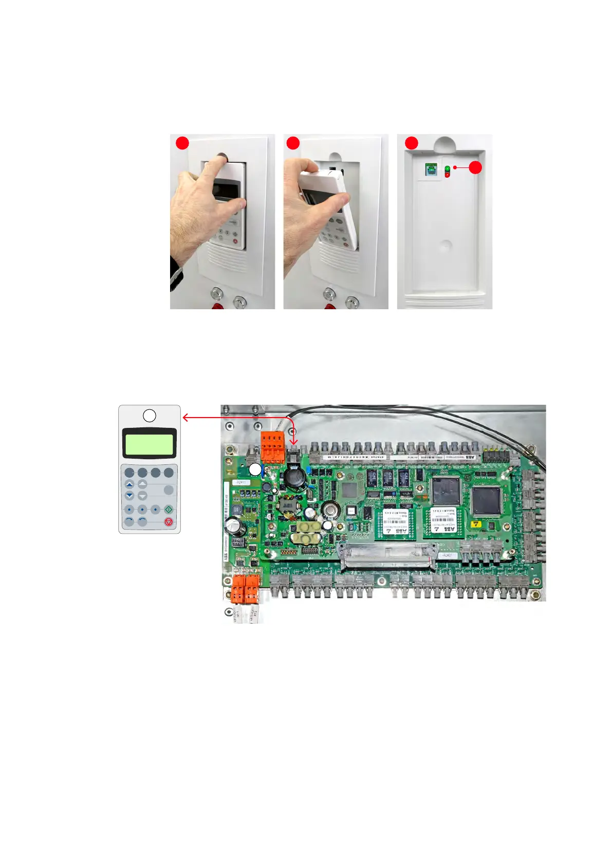
LEDs
The green LED (4) signals that the control voltage has been switched on.
Communication with AMC circuit board
The CDP control panel (1) is connected to the AMC circuit board (2) via an
RS485 interface.
10.5 LEDs and switches on circuit boards and I/O devices
The following section provides an overview of the meaning of LEDs and
switches of the main circuit boards and I/O modules. The LEDs presented
in the following section can be checked easily while the auxiliary voltage
is switched on without having to remove covers first. The LEDs provide
information on the status of the devices and can be used for
diagnostic purposes.
1
2 3
4
ACT PAR FUNC DRIVE
LOC
I0
RESET REF
ENTER
REM
1
2
 Loading...