max.
500 ohm
1…10 kohm
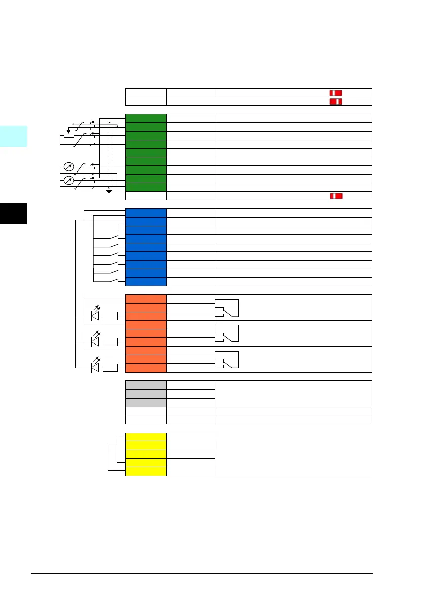
S1 AI1 U/I Voltage/Current selection for AI1:
S2 AI2 U/I Voltage/Current selection for AI2:
X1 Reference voltage and analog inputs and outputs
1 SCR Signal cable shield (screen)
2 AI1 Output frequency/speed reference: 0…10 V
3 AGND Analog input circuit common
4 +10V Reference voltage 10 V DC
5 AI2 Not configured
6 AGND Analog input circuit common
7 AO1 Output frequency: 0…20 mA
8 AO2 Output current: 0…20 mA
9 AGND Analog output circuit common
S3 AO1 I/U Voltage/Current selection for AO1:
X2 & X3 Aux. voltage output and programmable digital inputs
10 +24V Aux. voltage output +24 V DC, max. 250 mA
11 DGND Aux. voltage output common
12 DCOM Digital input common for all
13 DI1 Stop (0) / Start (1)
14 DI2 Forward (0) / Reverse (1)
15 DI3 Constant frequency/speed selection
16 DI4 Constant frequency/speed selection
17 DI5
Ramp set 1 (0) / Ramp set 2 (1)
18 DI6 Not configured
X6, X7, X8 Relay outputs
19 RO1C
Ready run
250 V AC / 30 V DC
2 A
20 RO1A
21 RO1B
22 RO2C
Running
250 V AC / 30 V DC
2 A
23 RO2A
24 RO2B
25 RO3C
Fault (-1)
250 V AC / 30 V DC
2 A
26 RO3A
27 RO3B
X5 EIA-485 Modbus RTU
29 B+
Embedded Modbus RTU (EIA-485)
30 A-
31 DGND
S4 TERM Serial data link termination switch
S5 BIAS Serial data link bias resistors switch
X4 Safe torque off
34 OUT1
Safe torque off. Factory connection. Both circuits
must be closed for the drive to start. See chapter
The Safe torque off function in ACS580-01 (0.75
to 250 kW) ardware manual (3AXD50000018826
[English]).
35 OUT2
36 SGND
37 IN1
38 IN2
1)
All control boards do not have switches S1, S2 and S3. In that case, select voltage or
current for inputs AI1
and AI2 and output AO1 with parameters. See the firmware manual.
Total load capacity of the Auxiliary voltage output +24V (X2:10) is 6.0 W (250 mA / 24 V DC).
Wire sizes:
0.2…2.5 mm
2
(24…14 AWG): Terminals +24V, DGND, DCOM, B+, A-, DGND, Ext. 24V
0.14…1.5 mm
2
(26…16 AWG): Terminals DI, AI, AO, AGND, RO, STO
Tightening torques: 0.5…0.6 N·m (0.4 lbf·ft)
1)
1)

 Loading...


