206 AO2000 CONTINUOUS GAS ANALYZERS | OI/AO2000-EN REV. B
Configuring the bar display or point display
Configuring the bar display or point display
1 Select menu item Display.
2 Start configuration of the new display element with NEW.
3 Select the parameter Source.
The function block menu is displayed.
4 Select the function block whose value is displayed.
When configuring the display, it does not matter if a link has been en-
tered for the function block.
5 For the parameters Name, Measuring point and Source, system
default values are displayed. The parameter Name cannot be changed.
6 Select the parameter Page.
The page overview is displayed.
7 Select the page on which the display element is to be displayed. Only
those pages can be selected with an assignment < 100 %, i.e. in which
there is at least one free position.
If the selected page is a system page, the position of the display ele-
ment is set by the system; it can only be changed using Swap Display
(see page 205).
If the selected page is a user page, the position must be configured.
8 Select the parameter Position.
The nine possible positions are graphically represented; free positions
are identified by the position number.
9 Select the position with the corresponding number key.
10 Select the parameter Type.
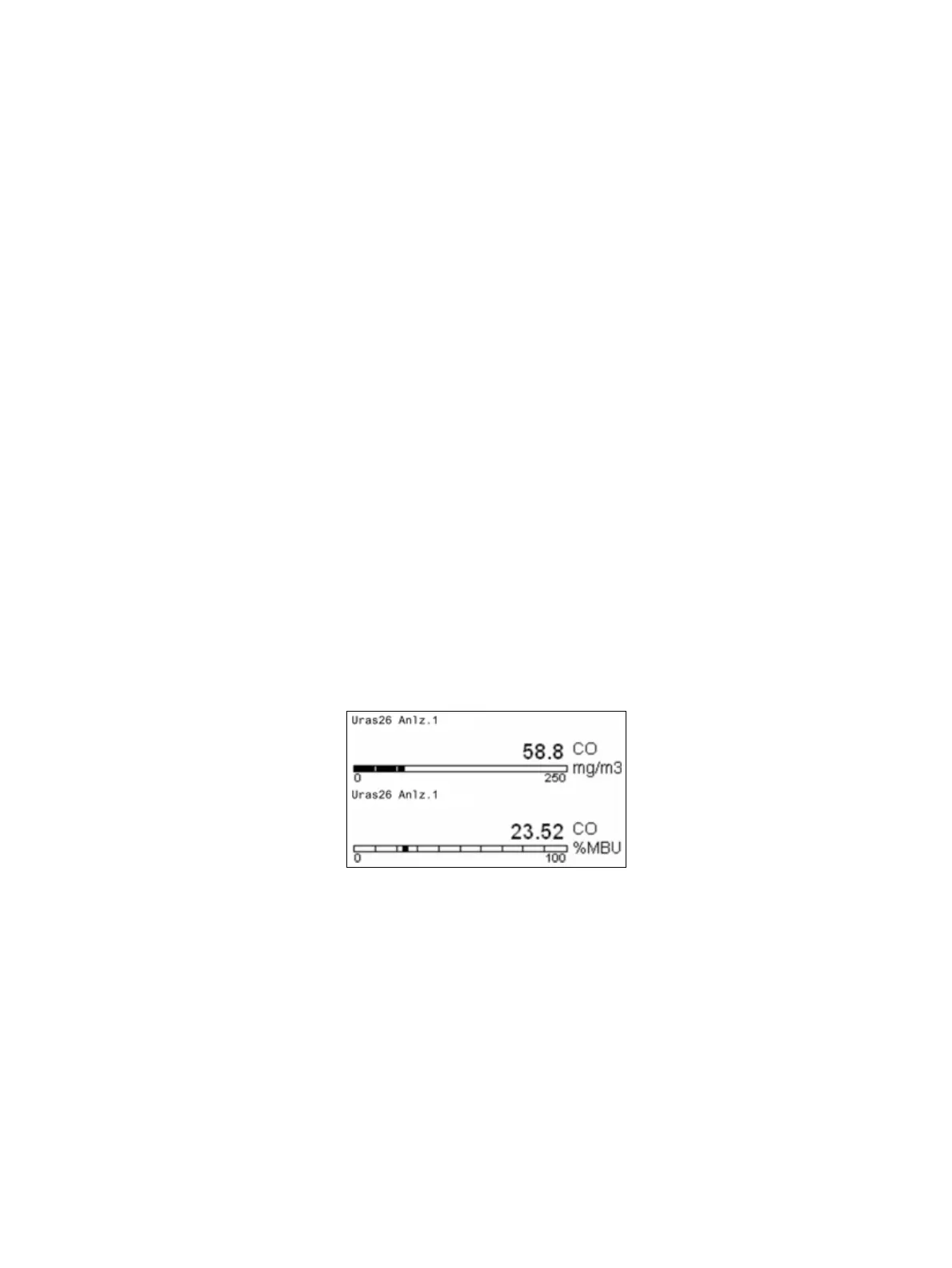
11 Select the display type:
Bar graph (top of the illustration) or Point graph (bottom of the
illustration).
12 Set the parameters Range Low, Range High and Places. If necessary,
change the description of the display element in the parameter Meas-
uring Point.
13 Switch to measuring mode.
The newly configured display element is now shown in the display. The
description of the display element is shown above the display. Shown to
the right of the display are the name and unit of the function block se-
lected in step 4. These two parameters can be changed by configuring
the function block.

 Loading...


