AO2000 CONTINUOUS GAS ANALYZERS | OI/AO2000-EN REV. B 77
Additional notes
• The connection box shown in the dimensional diagrams is
flange-mounted to the IP54 housing.
• Observe the installation location requirements (see page 37).
• The connecting lines require additional installation clearance (approx.
100 mm (3.94 in)).
• When installing the Fidas24 gas analyzer with heated sample gas con-
nection, note that the depth of the housing (without connection box) is
increased by approx. 76 mm (3 in) and that clearance is required for the
heated sample gas line (comply with minimum bending radius in ac-
cordance with manufacturer's instructions).
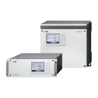
• When installing the wall-mount housing, note that clearance is required
on the left side to allow the door to swing open (approx. 60 mm (2.36 in)).
• When installing the wall-mount housing, note that additional clearance is
required above the housing, since some modules are only accessible
from above (approx. 300 mm (11.81 in)).
• The 19-inch housing and the wall-mount housing should be installed with
vertical orientation of the display.
• Multiple system housings in a 19-inch housing should be installed with a
separation of at least one height unit to ensure adequate air circulation.
 Loading...
