B60 Installation Guide
Test connection to device button
This button allows you to test the connection to the device to see if the sensor is working with the provided
Device ID and Register.
SCADA modbus start index
This indicates the SCADA register block associated with the specific sensor, once the device has been created
in the system. See “Automatic detection of Modbus sensors” on page B60 for more details.
Post-processing (opt)
This section allows you to apply corrections to the sensor’s basic values. The Slope value applies a multiplicative
factor to the basic value while the Bias value applies an additive factor to the basic value.
For example, for a sensor value of 100, if you enter 5 in the Slope field, you obtain a post-processing value of 500.
For the same sensor value of 100, if you enter 5 in the Bias field, you obtain a post-processing value of 105.
NOTICE
In situations where both values are used, the slope value is calculated first. To continue
with the example above, in a situation where you enter 5 for both Slope and Bias, the post-
processing value would be 505 (100×5+5) and not 125 (100+5×5).
Level validations
Level validations allows you to enable or disable maximum, minimum, warning, and alarm levels.
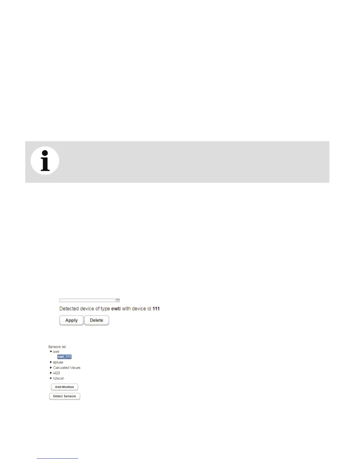
Automatic detection of Modbus sensors
The Detect Sensors button allows you to scan the Modbus network and add every sensor that responds to
the request based on the slave ID. Once those new detected sensors are added to the list, you can configure
and enable them to start the data acquisition process.
To automatically detect all Modbus sensors:
1 From the Sensor settings tab, click Detect Sensors. The system starts scanning for Modbus sensors; all
detected sensors appear in the Sensors list.
—
Figure 31 Scanning for sensors
—
Figure 32 Detected sensors
2 Simply select a detected sensor to configure it normally.

 Loading...