22 Fault tracing
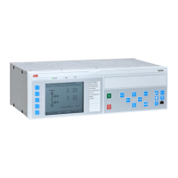
Status display of the control panel
Refer to the Firmware manual.
Warning and fault messages
Refer to the Firmware manual.
Control unit BCU-12 BATT OK Green The battery voltage of the real-time clock is OK
(more than 2.8 V).
When the LED off:
• The battery voltage is less than 2.8 V
• The battery is missing
• The control unit is not powered
PWR OK Green The internal voltage is correct.
FAULT Red The control program indicates that the equipment is
faulty.
Refer to the Firmware manual.
WRITE Yellow Writing to SD card in progress.
AC500 PWR Green The AC500 unit is powered.
RUN Green The AC500 program is running.
ERR Red An error or warning detected by the AC500
firmware.
MIRU-01 POWER Green The MIRU-01 unit is powered.
ERROR Red An error detected by the MIRU-01 firmware.
STATUS Green The status of the insulation resistance
measurement:
• Slow flash (once every 5 seconds):
Measurement ready
• Rapid flash (5 times per second):
Measurement not ready
DISABLE Red Insulation resistance measurement is disabled.
MGND-01 POWER Green The MGND-01 is powered.
GROUNDING
STATUS
Green The grounding voltage is OK (<50 V DC).
BAMU-11 POWER Green The BAMU-11 unit is powered.
LINK FAULT Red There is an error on the board or an error in the
PSL2 link.
U2 > 60V Yellow The input voltages (U2, V2 and W2) are more than
60 V.
U1 > 60V Yellow The input voltages (U1, V1 and W1) are more than
60 V.
Where LED Color Indication
 Loading...