grounding of the cable shields is recommended. Do not connect
the cable shields to ground at the sensor end of the cable.
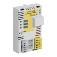
Terminal designations
DescriptionMarking
STO channel 1XSTO1
In, +24 V DC in for STO11
Out, +24 V DC out for STO12
STO channel 2XSTO2
In, +24 V DC in for STO21
Out, +24 V DC out for STO22
PTC FAULT (SMT function)XFLT
In, 0 … +5 V DCT1
OutT2
PTC WARNING (non-safety related)XWRN
In, 0 … +5 V DCT3
OutT4
Wiring
This section shows five methods to connect the FPTC-02 module to
the drive STO terminals.
Wiring example 1 (page 43): The STO outputs of the FPTC-02 module
are connected directly to the STO terminals of the drive.
• ACS880 drives and modules: In the factory-installed option
(+L537+Q971), the wiring is done at the factory according to this
example.
• ACS880 cabinet-built drives: In the option +L537+Q971, terminal
block [X969] is located between the module and the drive control
board (not shown in the figure). See the circuit diagrams delivered
with the drive for the actual wiring.
Wiring example 2 (page 44): The STO outputs of the FPTC-02 module
are connected to an FSO module, and the STO outputs of the FSO
module to the STO terminals of the drive with a two-channel
Electrical installation 41

 Loading...