3 Calibration
3.5. Calibration, axis 1, IRB 4400
453HAC 022907-001 Revision: -
Calibration, axis 1
The procedure below details how to perform the actual calibration of axis 1 using the special
calibration equipment.
CAUTION!
If the manipulator normally works in an inverted position, it must be removed from this
position and placed on the floor before the work detailed in this instruction may be carried
out !
Step Action Info/Illustration
1. Move the robot to its calibration position
corresponding to the calibration scales.
See section Calibration scales and
correct axis position on page 16.
2. Remove the cover plate on the reference
surface on the base of the robot.
Clean the surface with isopropanol and deburr it.
Art. no. is specified in Required
equipment on page 44.
3. Fit the calibration tool on the guide pin
underneath the gearbox.
Art. no. is specified in Required
equipment on page 44.
Shown in the figure Location of
calibration tool, axis 1 on page 44.
4. Fit the measuring pin to the calibration tool. Art. no. is specified in Required
equipment on page 44.
Shown in the figure Location of
calibration tool, axis 1 on page 44.
5. Release the brakes and move the robot
manually so that the measuring pin can be
placed in the guide hole on the base.
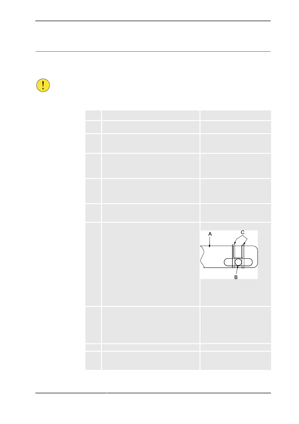
6. Put two guide bars on the tool and align the pin,
as shown in the figure to the right.
xx0300000203
• A: Calibration tool
• B: Measuring pin
• C: Guide bars
7. Update only axis 1. Detailed in sections
Fine calibration procedure on TPU
on page 65 (RobotWare 4.0).
Fine calibration procedure on
FlexPendant on page 67
(RobotWare 5.0).
8. Remove the calibration tool for axis 1.
9. Refit the cover plate to the reference surface on
the base of the robot, if no other calibration is to
be performed.
 Loading...