2 Installation and commissioning
2.4.5. Installation of position switch, axis 1
3HAC026660-001 Revision: C76
© Copyright 2006-2008 ABB. All rights reserved.
2.4.5. Installation of position switch, axis 1
General
This section details how to install the position switch to axis 1.
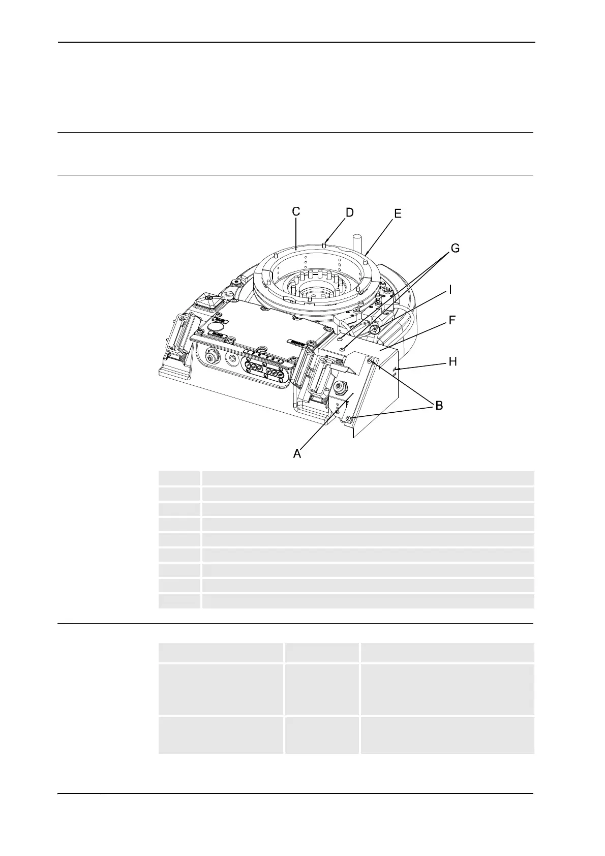
Location of position switch, axis 1
The position switch is installed between the frame and the base, as shown in the figure below.
xx0400001356
Required equipment
A Position switch
B Attachment screws, position switch, 2 pcs: M6 x 30
C Holder ring (2 parts)
D Attachment screws, holder ring, 6 pcs: M8 x 12
E Cam
F Bracket
G Attachment screws, housing, 2 pcs: M6 x 8
H Cable straps
I Attachment screws, attachment plate, 2 pcs: M6 x 16
Equipment Art. no. Note
Position switch, axis 1 3HAC023973-
001
Includes 3 switches.
All parts are included in the delivery.
Instruction of how to cut the cams is
enclosed in the kit.
Technical reference manual -
System parameters
(RobotWare 5.0)
Art. no. is specified in section References
on page 8.
Continues on next page
 Loading...