Chapter 4 – Electrical Installation
NCAN-02 Installation and Start-up Guide 4-5
CANopen Connection The bus cable and the external power supply are connected to terminal
blocks X1 and X2 on the NCAN-02.
The terminal blocks are described below.
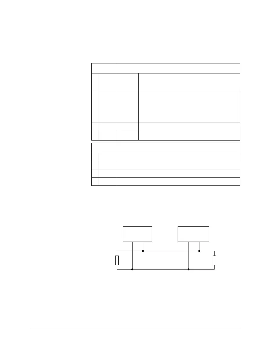
CAN Bus Termination The CAN bus line must be terminated with 120 ohm resistors
connected between the CAN_L and CAN_H wires at each end as
shown below.
X1 Description
1 0 V DC GND Power supply ground (0 V). If the power to the module is
supplied through the CAN network, this terminal should be
left unconnected.
2 UC +24 VDC +24 V ±10% (80 mA) DC supply to the module.
The power can be taken from the drive’s internal power
supply (see drive manuals), a dedicated external power
supply, or through the CAN network.
The on-board power supply is disabled if the voltage drops
below 11 V.
3
EXT
DC GND These terminals should be connected together if the
power to the module is supplied through the CAN network.
This makes the NCAN-02 a non-isolated node.
4
CAN GND
X2 Description
5 SHLD Network cable shield.
6 CAN_L CAN_L bus line.
7 GND CAN bus ground (digital ground).
8 CAN_H CAN_H bus line.
• • •
Node 1 Node n
120 ohm
CAN_H
CAN_L
1%, 1/4 W
120 ohm
1%, 1/4 W
 Loading...