- 87 -
000872BG
5 - Installation
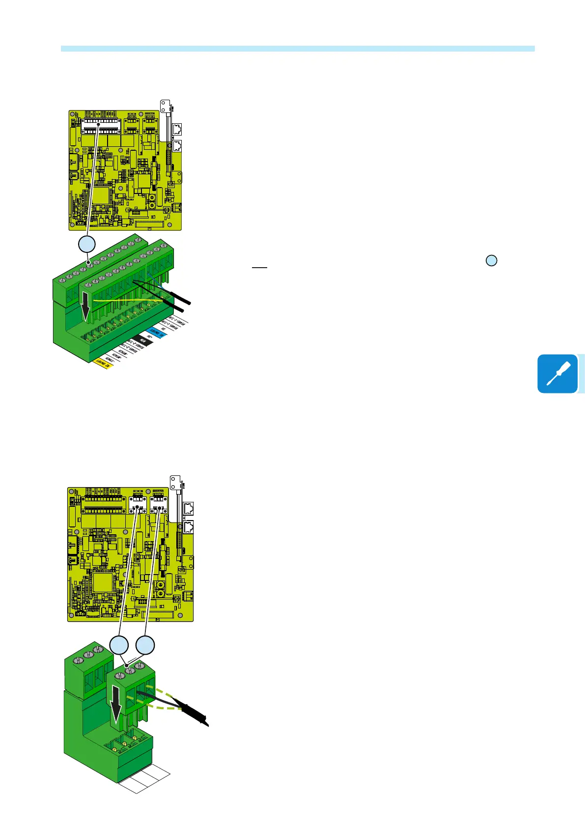
Remote control connection
The connection and disconnection of the inverter to and from the grid can
be controlled through an external control.
The function must be enabled in the relevant menu through the Aurora
Manager Tools software. If the remote control function is disabled, the
switching on of the inverter is dictated by the presence of the normal
parameters which allow the inverter to connect to the grid.
If the remote control function is operating, besides being dictated by the
presence of the normal parameters that allow the inverter to connect to the
grid, the switching on of the inverter also depends on the state of the R1
ON/OFF and R2 ON/OFF terminals compared to the RTN terminal present
on the a11 connector of the communication and control board
35
.
When one of the R1 ON/OFF or R2 ON/OFF signals is brought to the
same potential as the RTN signal (i.e. by making a short circuit between
the two terminals of the connector), this causes the inverter to disconnect
from the grid.
The connections of these controls are made between the “R1 ON/OFF”
and the "R1 ON/OFF" inputs compared to the common "RTN" signal.
Since this is a digital input, there are no requirements to be observed
as regards cable cross-section (it only needs to comply with the sizing
requirement for passing cables through the cable glands and the terminal
connector).
Configurable Relay connection (ALARM and AUX)
The inverter is equipped with 2 multifunction relays with congurable
activation. It can be connected with normally open contact (being
connected between the NO terminal and the common contact C) and
with normally closed contact (being connected between the NC terminal
and the common contact C).
Different types of devices (light, sound, etc.) can be connected to the
relay, provided they comply with the following requirements:
Alternating current
Maximum Voltage: 240 V AC Maximum Current: 1 A
Direct current
Maximum Voltage: 30 V DC Maximum Current: 0.8 A
Cable requirements
External diameter: from 5 to 17 mm
Conductor cross-section: from 0.14 to 1.5 mm
2
This contact can be used in different operating congurations that can be
selected by accessing the embedded web server.
J1
J18
J8
X5
J9 J10 J11 J12
J16
A5
J14
J13
S6
J20
J17
J21
J7
J18
J2
S5
S7
J5
J24
K5
S9
S8
T5
J27
J6
J19
J22
K6
J25
J15
J3
8
9
0
5
6
7
NCCOM
NO
NCCOM
NO
1
2
3
4
1
2
3
4
8
9
0
5
6
7
OFFON
PC2
OFFON
PC1
R2 ON/OFF
R1 ON/OFF
53
J1
J18
J8
X5
J9 J10 J11 J12
J16
A5
J14
J13
S6
J20
J17
J21
J7
J18
J2
S5
S7
J5
J24
K5
S9
S8
T5
J27
J6
J19
J22
K6
J25
J15
J3
8
9
0
5
6
7
NCCOM
NO
NCCOM
NO
1
2
3
4
1
2
3
4
8
9
0
5
6
7
OFFON
PC2
OFFON
PC1
NC
NO
C
52 51
 Loading...


