34
1MRS750527-MUM
Feeder Terminal
Technical Reference Manual, General
REF 54_
5.1.5. Auxiliary voltage
For its operation the REF 54_ terminal, including the external display module,
requires a secured auxiliary voltage supply. The feeder terminal’s internal power
supply module forms the voltages required by the feeder terminal electronics. The
power supply module is a galvanically isolated (flyback-type) DC/DC converter. A
green protection LED indicator on the front panel is lit when the power supply
module is in operation.
The feeder terminal is provided with a 48-hour capacitor back-up protection
1
that
enables the internal clock to keep time in case of an auxiliary power failure.
5.1.5.1. Power supply versions
There are two basic types of power supply modules available for the REF 54_ feeder
terminals: type PS1/_ and type PS2/_. The module PS1/_ is used in REF 541 and
REF 543 terminals. The module PS2/_ is intended for the REF 545 terminal. Both
modules are available in two versions: PS1/48 V, PS1/240 V, PS2/48 V, PS2/240 V.
There are also differencies in the threshold voltages of the power supply modules’
digital inputs. PS1/_ has three different alternatives for threshold voltage of the
binary inputs: low, medium and high version. The threshold voltage of the low
version is 18 V DC, medium version 80 V DC and high version 155 V DC. The
module PS1/48 V is a low version power supply and PS1/240 V is a medium or high
version. The type PS2/_ does not have binary inputs.
When REF 54_ is delivered with a fixed display module, the input voltage range of
the power supply module is marked on the front panel of the feeder terminal. When
the feeder terminal is provided with an external display module, the input voltage of
the display module is marked on the front panel of the module and the input voltage
of the main unit is marked on the side of the unit.
The main unit and the external display module must each be
provided with separate power supply from a common source.
1. This function is only supported in the feeder terminal revisions of Release 2.0 or
later,
refer to Section “Revision identification” on page 105.
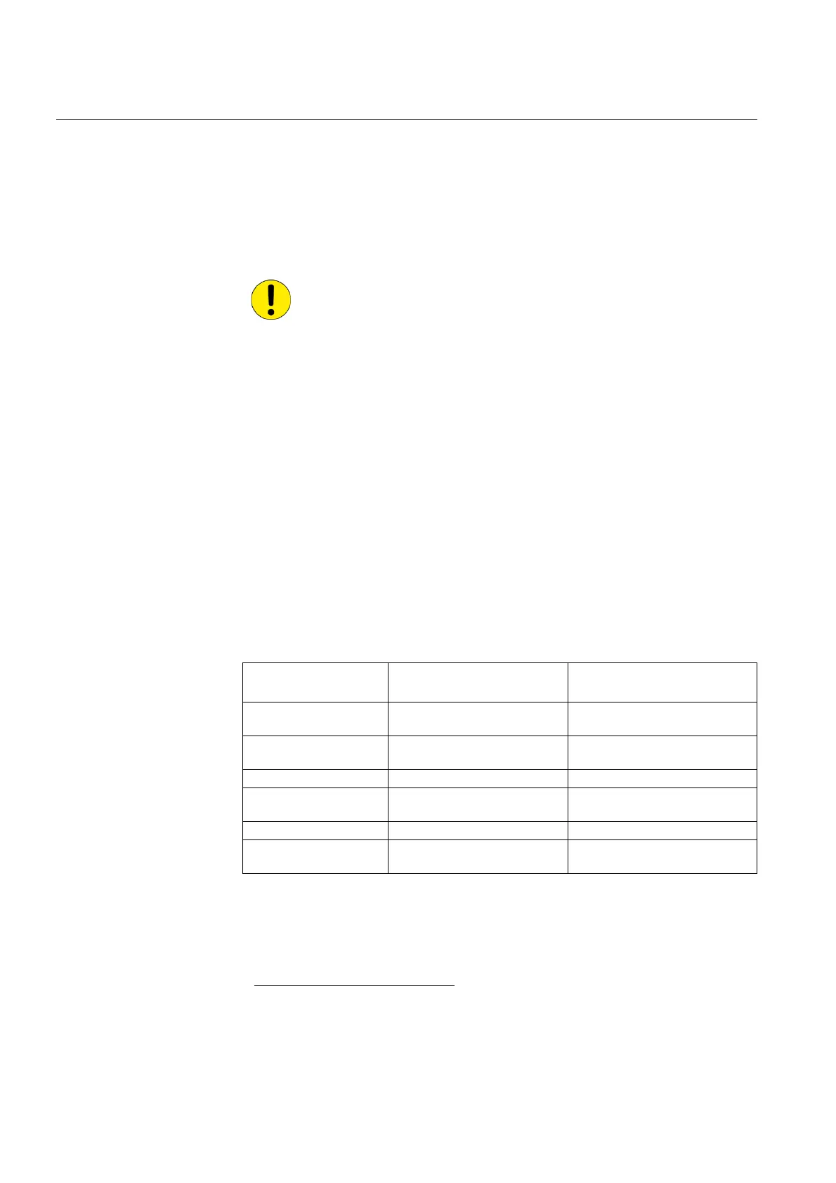
Table 5.1.5.1-1 Power supply modules and their rated input voltages
Power supply module
Rated input voltage
of power supply
Rated input voltage
of digital inputs
PS1/240 V (High) 110/120/220/240 V AC
or 110/125/220 V DC
220 V DC
PS1/240 V (Medium) 110/120/220/240 V AC
or 110/125/220 V DC
110/125/220 V DC
PS1/48 V (Low) 24/48/60 V DC 24/48/60/110/125/220 V DC
PS2/240 V 110/120/220/240 V AC
or 110/125/220 V DC
-
PS2/48 24/48/60 V DC -
External display module 110/120/220/240 V AC
or 110/125/220 V DC
-

 Loading...


