38
1MRS750527-MUM
Feeder Terminal
Technical Reference Manual, General
REF 54_
The letters b and c after the signal type are used to distinguish between signals of the same type.
5.1.6.1. Scaling the rated values of the protected unit for analog
channels
A separate scaling factor can be set for each analog channel. The factors enable
differences between the ratings of the protected unit and those of the measuring
device (CTs, VTs and so on) The setting value 1.000
1
means that the rated value of
the protected unit is exactly the same as that of the measuring device.
When scaling factors are used, it should be noted that they affect the operation
accuracy and the dynamic measuring range of the terminal. The accuracies stated in
the description of each function block (see the CD-ROM “Technical Descriptions of
Functions”) only apply with the default values of the scaling factors. For example,
a high factor affects the operation of sensitive protection functions, such as the
directional earth-fault protection.
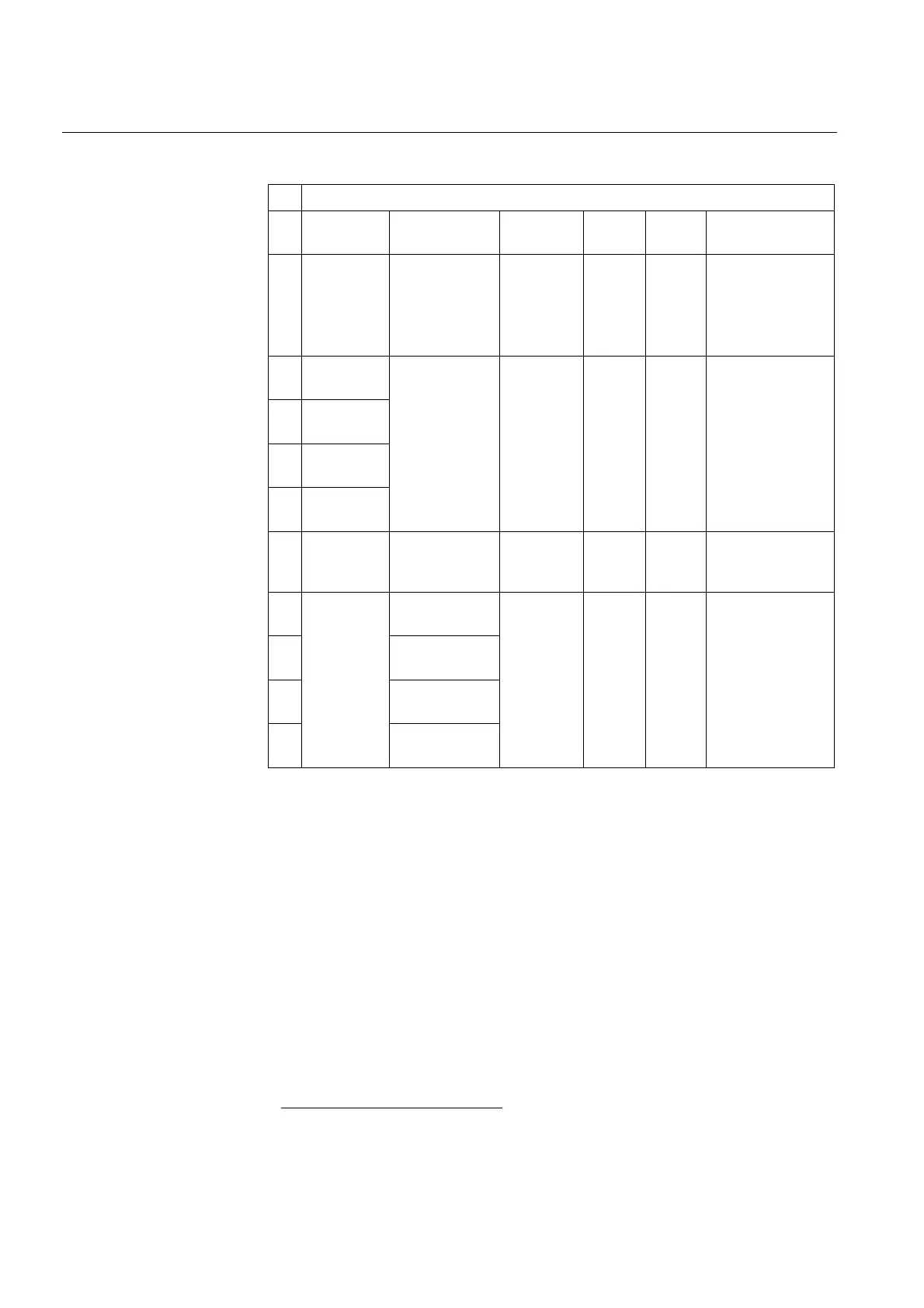
Table 5.1.6-1 Physical analog channels of the feeder terminals
Measuring units
Ch
No.
Current
Transformer (CT)
Voltage Transformer
(VT)
Rogovski coil/-
sensor (RS)
Voltage
divider (VD)
General
measure-
ment
Signal type (selectable
alternatives)
1
RS 1...10 VD 1...10 Gen. meas.
1...3
Not in use,
I
L1
, I
L2
, I
L3
,
I
L1b,
I
L2b,
I
L3b,
U
1
, U
2
, U
3
,
U
1b
, U
2b
, U
3b
,
U
1c
,
GE1, GE2, GE3
2
Current
Transformer CT1
(I
n
= 1 A/5 A)
RS 1...10 VD 1...10 Gen. meas.
1...3
Not in use,
I
L1
, I
L2
, I
L3
,
I
L1b,
I
L2b,
I
L3b,
I
0
, I
0b
,
U
1
, U
2
, U
3
,
U
1b
, U
2b
, U
3b
,
U
1c
,
GE1, GE2, GE3
3
Current
Transformer CT2
(I
n
= 1 A/5 A)
4
Current
Transformer CT3
(I
n
= 1 A/5 A)
5
Current
Transformer CT4
(I
n
= 1 A/5 A)
6
Current
Transformer CT5
(I
n
= 0.2 A/1 A)
Not in use,
I
L1
, I
L2
, I
L3
,
I
L1b,
I
L2b,
I
L3b,
I
0,
I
0b
7
Voltage Transformer
VT1 (U
n
=100V/110V/
115V/120V)
RS 1...10 VD 1...10 Gen. meas.
1...3
Not in use,
I
L1
, I
L2
, I
L3
,
I
L1b,
I
L2b,
I
L3b,
U
12
, U
23
, U
31
,
U
12b
, U
23b
, U
31b
,
U
12c
,
U
1
, U
2
, U
3
,
U
1b
, U
2b
, U
3b
,
U
1c
,
U
0
, U
0b
,
GE1, GE2, GE3
8
Voltage Transformer
VT2 (U
n
=100V/110V/
115V/120V)
9
Voltage Transformer
VT3 (U
n
=100V/110V/
115V/120V)
10
Voltage Transformer
VT4 (U
n
=100V/110V/
115V/120V)
1. Prior to Release 2.5 with two decimals only.

 Loading...


