1MRS750527-MUM
REF 54_
43
Feeder Terminal
Technical Reference Manual, General
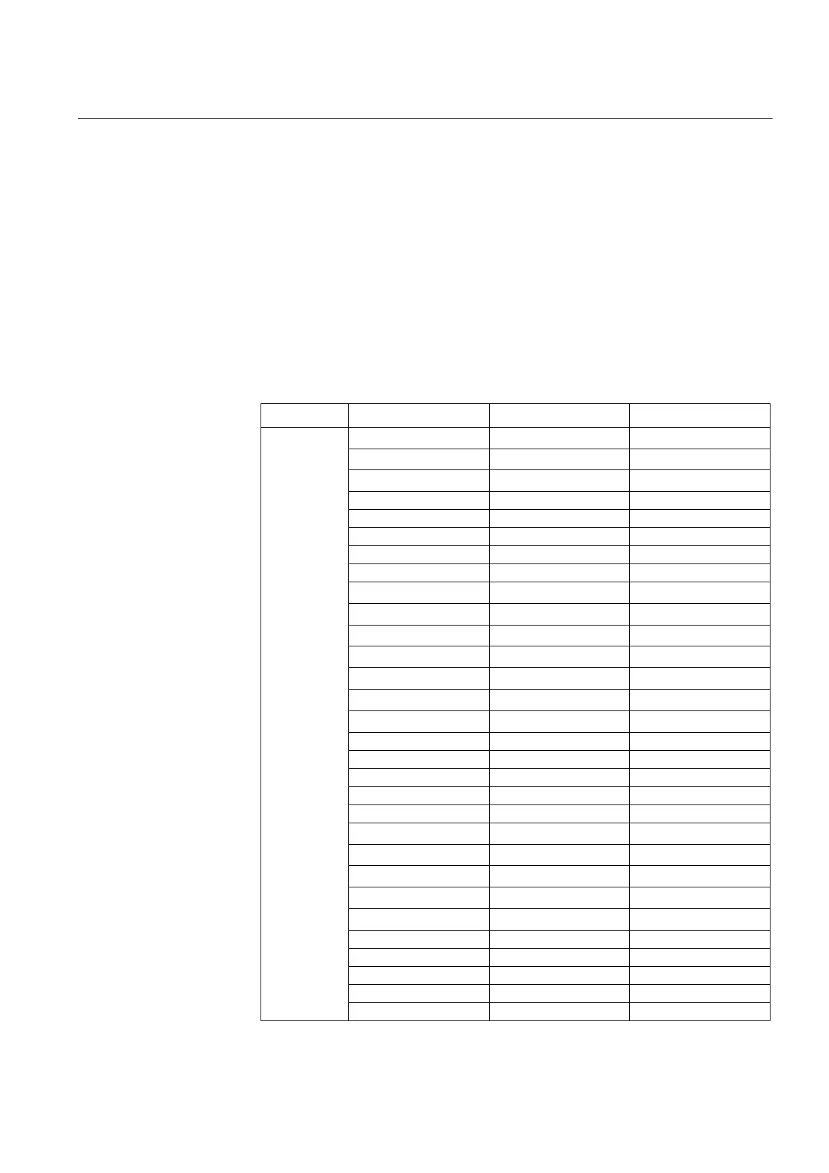
5.1.7. Digital inputs
The REF 541, REF 543 and REF 545 feeder terminals differ from each other
regarding the number of digital inputs available.
The digital inputs of the REF 54_ feeder terminals are voltage-controlled and
optically isolated. For technical data of the digital inputs, refer to
Table 5.2.1-3 on
page 89.
The parameters for input filtering, input inversion and pulse counters (see sections
below) can be set in the Configuration menu under each I/O card (for example
Configuration/BIO1/Input filtering).
The events and parameters of I/O cards are included in the event and parameter lists
on the CD-ROM “Technical Descriptions of Functions” (
refer to Section “Related
documents” on page 10).
Table 5.1.7-1 Digital inputs available for the REF 54_
REF 541 REF 543 REF 545
Inputs
PS1_4_BI1
1)
PS1_4_BI1
1)
BIO1_5_BI1
PS1_4_BI2
1)
PS1_4_BI2
1)
BIO1_5_BI2
PS1_4_BI3
1)
PS1_4_BI3
1)
BIO1_5_BI3
BIO1_5_BI1 BIO1_5_BI1 BIO1_5_BI4
BIO1_5_BI2 BIO1_5_BI2 BIO1_5_BI5
BIO1_5_BI3 BIO1_5_BI3 BIO1_5_BI6
BIO1_5_BI4 BIO1_5_BI4 BIO1_5_BI7
BIO1_5_BI5 BIO1_5_BI5 BIO1_5_BI8
BIO1_5_BI6 BIO1_5_BI6
BIO1_5_BI9
1)
BIO1_5_BI7 BIO1_5_BI7
BIO1_5_BI10
1)
BIO1_5_BI8 BIO1_5_BI8
BIO1_5_BI11
1)
BIO1_5_BI9
1)
BIO1_5_BI9
1)
BIO1_5_BI12
1)
BIO1_5_BI10
1)
BIO1_5_BI10
1)
BIO1_6_BI1
BIO1_5_BI11
1)
BIO1_5_BI11
1)
BIO1_6_BI2
BIO1_5_BI12
1)
BIO1_5_BI12
1)
BIO1_6_BI3
BIO2_7_BI1 BIO1_6_BI4
BIO2_7_BI2 BIO1_6_BI5
BIO2_7_BI3 BIO1_6_BI6
BIO2_7_BI4 BIO1_6_BI7
BIO2_7_BI5 BIO1_6_BI8
BIO2_7_BI6
BIO1_6_BI9
1)
BIO2_7_BI7
BIO1_6_BI10
1)
BIO2_7_BI8
BIO1_6_BI11
1)
BIO2_7_BI9
1)
BIO1_6_BI12
1)
BIO2_7_BI10
1)
BIO2_7_BI1
BIO2_7_BI2
BIO2_7_BI3
BIO2_7_BI4
BIO2_7_BI5
BIO2_7_BI6

 Loading...


