44
1MRS750527-MUM
Feeder Terminal
Technical Reference Manual, General
REF 54_
1) These digital inputs can be programmed as either digital inputs or pulse counters, refer to Section
“Pulse counters” on page 45.
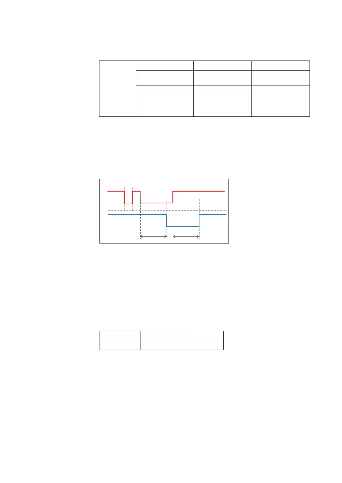
5.1.7.1. Filter time of a digital input
The filter time eliminates debounces and short disturbances on a digital input. The
filter time is set for each digital input of the REF 54_ feeder terminal. The operation
of input filtering is illustrated below.
dipo_b
Fig. 5.1.7.1.-1 Filtering of a digital input
In the figure above, the input signal is named ‘Input’, the filter timer ‘Filter Time’
and the filtered input signal ‘Filtered Input’. At the beginning, the input signal is at
high state, the short low state is filtered and no input state change is detected. The
low state starting from the time t
0
exceeds the filter time, which means that the
change in the input state is detected and the time tag attached to the input change is
t
0
. The high state starting from t
1
is detected and the time tag t
1
is attached.
Each digital input has a filter time parameter “Input # filter”, where # is the number
of the digital input of the module in question (for example Input 1 filter).
1)
In the feeder terminal revisions of Release 2.5 or later. Before Release 2.5: 1...65535 ms.
BIO2_7_BI7
BIO2_7_BI8
BIO2_7_BI9
1)
BIO2_7_BI10
1)
Digital inputs /
total
15 25 34
Table 5.1.7-1 Digital inputs available for the REF 54_ (Continued)
REF 541 REF 543 REF 545
Parameter Values Default
Input # filter
1....15000 ms
1)
5 ms
t
0
t
1
Filter Time
Filtered Input
Input
Filter Time

 Loading...


