S800 I/O Station Data Scanning Section 3 Technical Data and Performance
138 3BSE015969-600 A
Calculation of Bus Cycle Time
How to calculate the Bus Cycle Time, see documentation for current master.
To calculate the Bus Cycle Time the following parameters for the I/O station shall
be used:
Number of input and output bytes.
MAX T
SDR
Maximum Station Delay of Responder in T
BIT
(Bit Time).
See GSD file.
S800 I/O Station Data Scanning
The ModuleBus data is scanned (read or written) cyclically, depending on the I/O
module configuration. To calculate the I/O scan cycle time in the FCI do as follows:
Totalize (number of module type x) * (used execution time for type x)
(see Table 28) if the value is a multiple of 2, add 2 to the value. Otherwise increase
the total value to the nearest higher multiple of 2 to get the I/O scan cycle time.
If CI810A or C1810B is used, the scan cycle time is increased by 25% and for
CI820 it is increased by 50%. If the value is a multiple of 2, add 2 to the value.
Otherwise increase the value to the nearest higher multiple of 2, to get the I/O cycle
time.
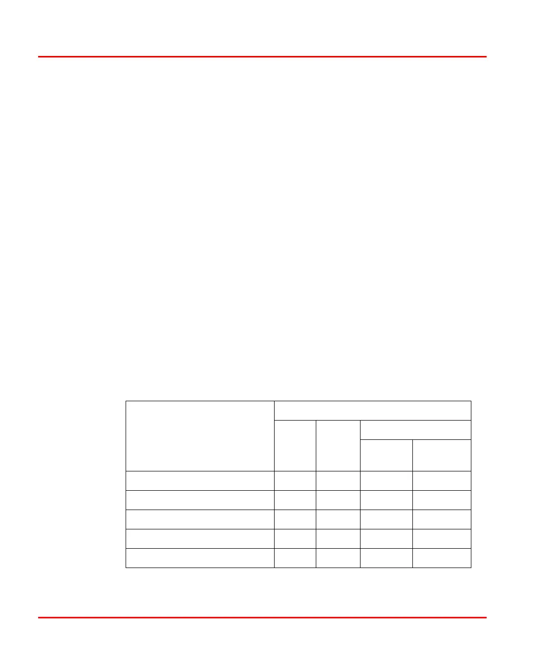
Table 28. I/O Scan Cycle Time in the FCI
Module Type
Execution Time Used in ms
CI801
CI810,
CI820
CI840
Single I/O
Redundant
I/O pair
AI801, AI810, AI890, AI895 3.00 3.00 3.00 -
AI820 1.50 1.50 1.50 -
AI825 1.50 - 1.50 -
AI830, AI830A, AI835, AI835A 0.40 0.40 0.40 -
AI893 0.40 - 0.40 -

 Loading...