Section 3 Technical Data and Performance Calculation of Maximum Distance of an Optical
3BSE015969-600 A 143
Calculation of Maximum Distance of an Optical ModuleBus Configuration
Calculation of Maximum Fibre length for TB825
The maximum signal delay should be calculated in the configuration using Optical
ModuleBus Media Converter. This is calculated using the signal path from the
controller to the point in the configuration that has the longest delay. The maximum
delay in an optical ModuleBus configuration must be 100
µs (less than 250µs for
S800 I/O HI).
The delay values in Table 29 can be used to calculate the maximum delay in an
optical ModuleBus configuration.
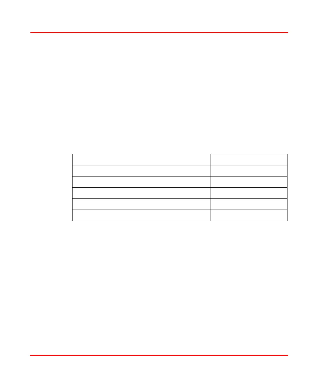
Table 29. Delay Values Optical ModuleBus Components
Opto-to-opto delay in TB825
(1)
(1) Notice that the delays in the table is the sum of the communication delay in both directions, i.e.
(delay of master frame) + (delay of slave frame).
2.4 µs
Opto-to-opto delay in TB820/TB820V2(1) 4.0 µs
Opto-to-electrical delay in TB820/TB820V2(1) 6.5 µs
Opto-to-opto delay in TB840/TB840A
(1)
2.0 µs
Opto-to-electrical delay in TB840/TB840A
(1)
5.5 µs
Delay in optical fiber
(1)(2)
(2) Total fiber length = total local fiber length + field fiber length
(0.01 x length) µs

 Loading...