39
11
3
29
21
20
2, 2a 10
13
37
1 14
12
27
39
15
19
6459
16
23
26
12a
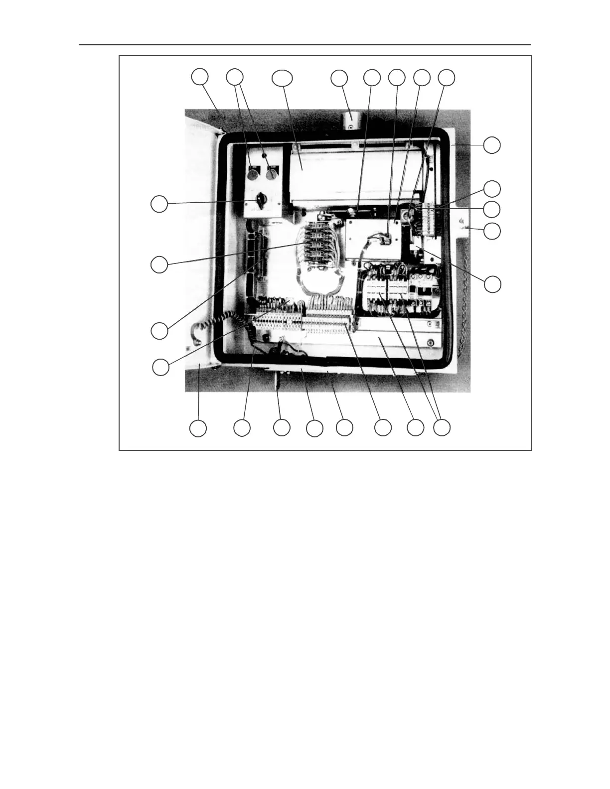
Figure 1 : Inside view of motor-operated mechanisms type MT 50 and MT 100
1 Motor (with cover 1a)
2 Operating spindle (with cover 2a) and gear-train
3 Auxiliary switch
4 Mounting plate
5 Terminal strip
6 Control contractor
9 Supply lead plate
10 Operating shaft
12 Housing (with door 12a)
13 Control disc
14 Safety contract
15 Cover for emergency operation
16 Venting hole with filter insert for ventilation
19 Blocking magnet
20 Push button (open & close)
21 Gasket
23 Earthing connection angle
26 Flexible earthing connection
27 Terminals
29 Changeover switch
37 Rectifier
39 Varistor
5/16
1 HDU 05004-YN Rev. C

 Loading...


