15. Mounting of Mechanical Interlocking
Caution : The interlocking segments, the operating mechanism for the disconnector and the operating
mechanism for the earthing switch must be mounted together on one pole.
For rated voltages 245 ... 362 kV : If the disconnector poles are arranged in parallel, the coupling rods
(15) must always be mounted on the same side on which the earthing switch is mounted.
Note : Mechanical interlocks between disconnector and earthing switch are mounted at the factory.
Retrofitting is not possible.
Note : Make sure that the disconnector is in the ON position before mounting the mechanical interlock
and that the earthing switch is in the OFF position.
Mounting steps :
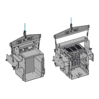
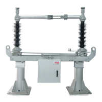
1. Mount interlocking segment (349) with clamping cover (334) on earthing-switch shaft (337 or 73)
in case of parallel arrangement or series arrangement of the disconnector poles Figure 65
2. With the disconnector in the ON position and the earthing switch in the OFF position, try to set
the earthing switch manually to the ON position. The interlock must block.
3. Set disconnector manually to the OFF position.
4. Set earthing switch manually to the ON position, ensuring that there is sufficient distance
between interlocking lever (350, 351) and earthing-switch link (336) Figure 65
5. Tighten locking screw in interlocking segment (349) and secure with lock nut Figure 65
6. Next step : Chapter 16 : Commissioning
A
A
A
A
76/113
1HDB 050016-YN-A
 Loading...
