Contents of Figures
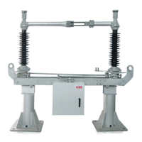
Figure 1 : 3-pole type SGF two-column rotary disconnector
in parallel arrangement (basic design) .................................... 3
Figure 2 : 3-pole type SGF two-column rotary disconnector
In series arrangement (basic design) ...................................... 3
Figure 3 : Basic design of type SGF two-column rotary disconnector ...... 4
Figure 4 : Basic design of earthing switch ............................................... 5
Figure 5 : Mode of operation
Of type SGF two-column rotary disconnector
(Example : 3-pole in parallel arrangement) .............................. 6
Figure 6 : Mode of operation of earthing switch
(Example : 3-pole in parallel arrangement).............................. 7
Figure 7 : General main dimensions
Of type SGF two-column rotary disconnector .......................... 9
Figure 8 : Minimum distances P
min
Between poles of disconnector in parallel arrangement ........... 10
Figure 9 : Minimum distances Pmin
Between poles of disconnector in series arrangement ............ 10
Figure 10 : Scope of supply, disconnector ................................................ 11
Figure 11 : Scope of supply, earthing switch ............................................. 12
Figure 12 : Mounting of disconnector :
Shipping of disconnecetor base (2)
If mounting on supporting structure ......................................... 17
Figure 13 : Mounting of disconnector:
Shipping of premounted disconnector pole
If mounting in front of supporting structure
(Example : Version for rated normal current 1 600 A) ............... 17
Figure 14 : Mounting of disconnector ....................................................... 18
Figure 15 : Mounting of disconnector :
Mounting of corona-protection fittings (87) on rotary heads
(Only for rated voltage 300 & 362 kV) ..................................... 19
Figure 16 : Mounting of disconnector :
Mounting of corona-protection fittings (7) on finger side
(Only for rated voltages 245......362 kV) .................................. 20
Figure 17 : Mounting of disconnector :
Mounting of corona-protection fittings (7) on contact side
(Only for rated voltages 245 ... 362 kV) .................................... 21
Figure 18 : Mounting of operating mechanism for disconnector :
Direct mounting ...................................................................... 23
Figure 19 : Mounting of operating mechanism for disconnector,
Direct mounting : Mounting of operating lever (74)
If operating mechanism for disconnector
At operating side ..................................................................... 24
Figure 20 : Mounting of operating mechanism for disconnector,
Direct mounting : Mounting of operating lever (74)
If operating mechanism for disconnector
at opposite opening side ......................................................... 25
Figure 21 : Mounting of operating mechanism for disconnector,
Separate mounting : Measurement m3 < 6 m .......................... 27
Figure 22 : Mounting of operating mechanism for disconnector
Separate mounting if measurement m3 <, 6 m :
Mounting dimensions ............................................................. 28
Figure 23 : Mounting of operating mechanism for disconnector,
Separate mounting if measurement m3 = 6 .. 12 m :
Mounting dimensions ............................................................. 29
iii
1HDB 050016-YN-A
 Loading...
