14
TruONE® ATS, INSTALLATION AND OPERATING INSTRUCTION
1
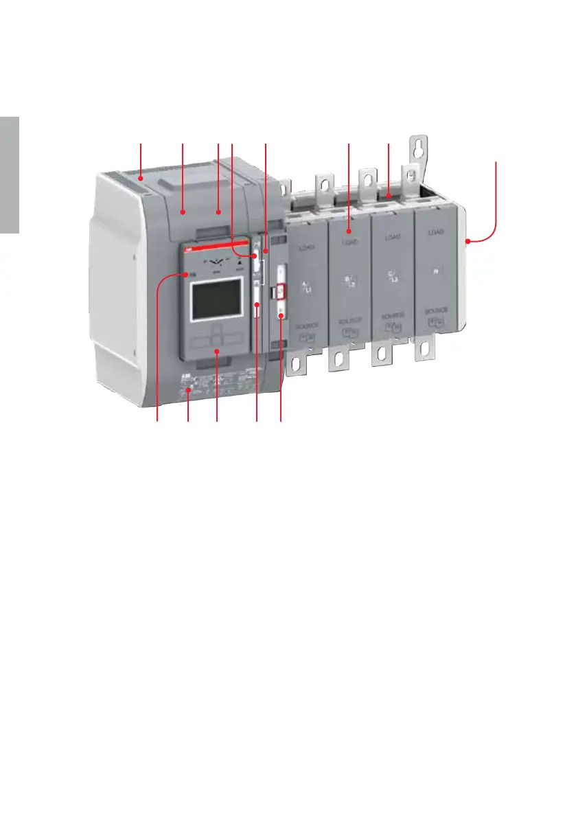
1 Transfer switch
2 Embedded ATS control unit and mechanism
3 Detachable HMI unit, three types of control interfaces Level 2 (DIP), Level 3 (LCD)
and Level 4 (touch) for configuration and automatic operation
4 Slide switch (Hand - Locking - AUTO) for selection of the operation mode
5 Padlocking the automatic transfer switch to prevent automatic and manual
operation. Note: Slide switch (Hand - Locking - AUTO) has to be in Locking-position
6 Handle for manual operation
7 Position indication
8 Terminals for control circuit connections (behind the cover)
9 Place for connectivity modules (aux power supply, communication and signaling)
10 Place for sensor module (included as standard with Level 4 controls)
11 Place for auxiliary contact blocks
12 Product identification label
13 Programming port, only for Ekip Programming and Ekip Bluetooth-modules
11
2
3 5 7
6
8 9 1
12
10
13
4
—
Fig. 2.1 Automatic transfer switch, TruONE® ATS, type OXB_B
—
2.1 General overview

 Loading...