EasyManuals Logo
Home>ABB>Controller>UMC100.3

ABB UMC100.3 User Manual

ABB UMC100.3
160 pages
To Next Page IconTo Next Page
To Previous Page IconTo Previous Page
Page #21 background imageLoading...
Page #21 background image
Power

1C a 1 C b
2C a 2C b
RDY
Diag
ERR
0V 24V DC Adr
I2a I2b I2c
I1a I1b I1c
I3a I3b I3c
Lo gic
/
µ C
24VDC
Diag
Ready
0V
Error
RX / TX
1CA
2CA
1CB
2CB
AI111
Adr
I
I
I
I1a
I1b
I1c
I2a
I2b
I2c
I3a
I3b
I3c
υ
I1a
I1b
I1c
υ
I1a
I1b
I1c
A
V
+
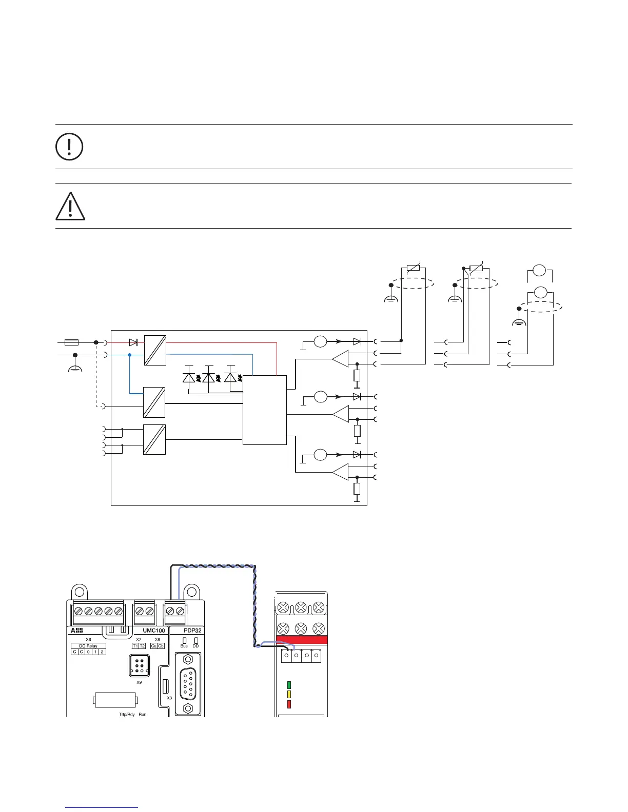
Connecting the AI111.0 Inputs
The module AI111.0 allows to measure three temperatures, voltage (0...10V) and current (0/4...20mA).
The diagram below shows the block diagram and wiring of the analog input module.
It is possible to connect up to two AI111 modules to the UMC100.3. Connect the Adr terminal to 24V DC at the
second module.
Avoid parallel runs of power cables or other noise sources to the analog input signal cables. It is recommended to
use shielded cables (see technical data).
Connection between UMC100.3 and the AI111 module
Connection cable:
UMCIO-CAB.030CAB
Wiring diagram of the AI111 modules. Depending on the analog input source choose the correct terminals
21
INSTALL ATION

Table of Contents

Questions and Answers:

Question and Answer IconNeed help?

Do you have a question about the ABB UMC100.3 and is the answer not in the manual?

ABB UMC100.3 Specifications

General IconGeneral
BrandABB
ModelUMC100.3
CategoryController
LanguageEnglish

Related product manuals