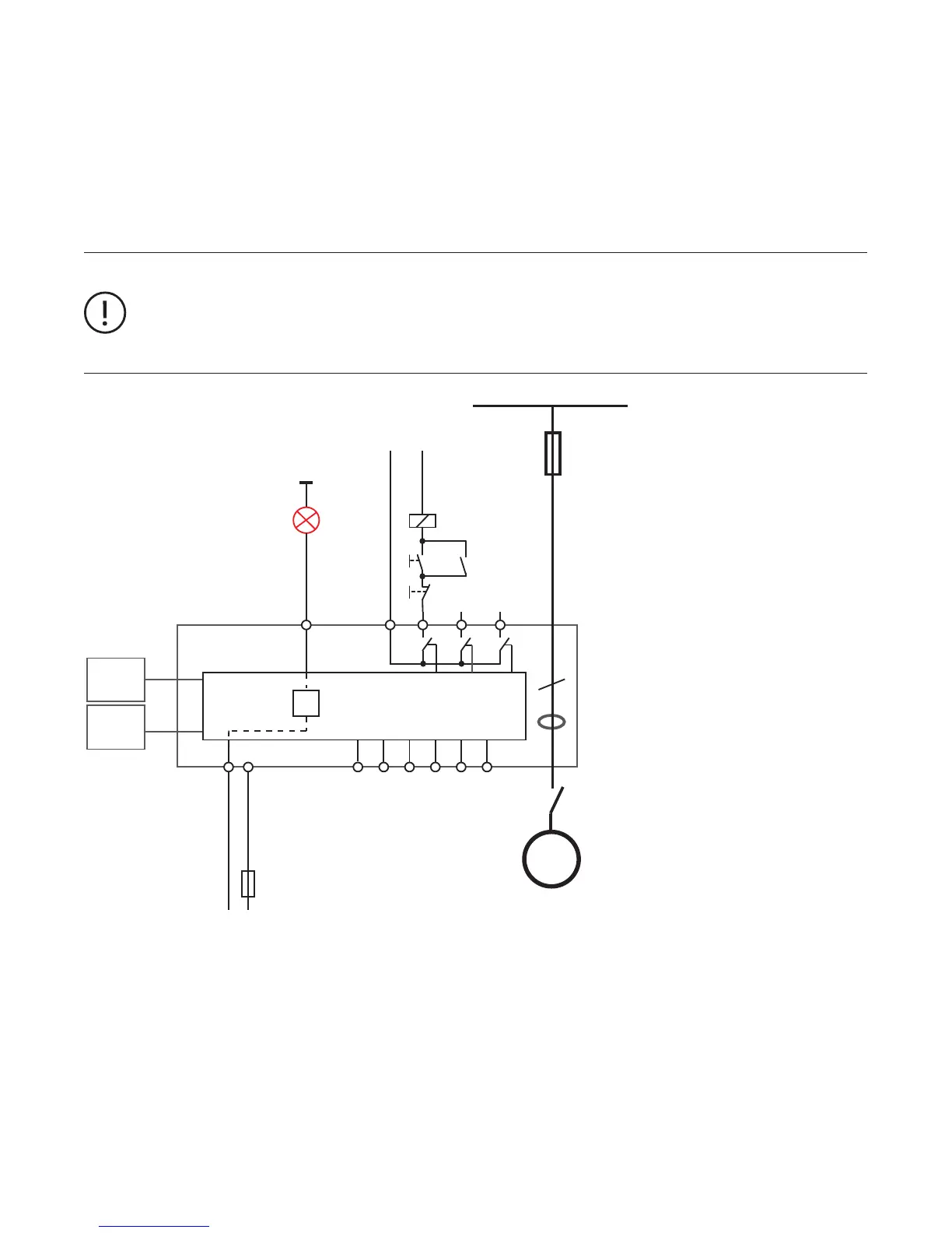
Control Function Overload Relay
The UMC100.3 parameterised with the control function 'Overload relay' can be used to replace a standard overload relay. The out-
puts DO2 ... DO3 and the inputs DI0 ... DI5 are directly connected to the fieldbus and not used from the control function. If a fault
output is activated the fault output (DO2 or 24 V DC Out DO3) cannot be controlled from the fieldbus anymore but is controlled by
the UMC itself. After powering up, contact DO0 immediately closes and contact DO1 opens.
The following features are not supported in this control function:
• Checkback supervision
• UMC controlled starting and stopping (bus, LCD, DI)
• Simulation and stop via multifunction inputs
• Bus fault reaction
• Voltage dip
—
Circuit diagram of the UMC overload relay mode
Fault Behaviour:
• Contact DO0 opens
• Contact DO1 closes
• The fault output DO2/DO3 is activated if configured
• The monitoring signal FAULT is sent to the fieldbus
• The red LED on the UMC is switched on
• The FAULT signal on the control panel flashes
L1, L2, L3
M
3
Contactor
Supply
(e.g. 230VAC)
K1
k1
DOC DO0 DO1 DO2
24VDC
24VDC
DO3
DI0 DI1 DI2 DI3 DI4 DI5
UMC100
UMC-
PAN
Comm.
Interface
0V
I
Lim
GND
(24VDC)
k1
On
Off
Supply
0V/24V
72
 Loading...