M
3
Contactor
Supply
(e.g. 230VAC)
K81
DOC DO0 DO1 DO2
24VDC
24VDC
DO3
DI0 DI1 DI2 DI3 DI4 DI5
UMC100
UMC-
PAN
Comm.
interface
0V
I
Lim
Speed1
Stop
GND
(24VDC)
K91
k91k81
K81=speed one
K91=speed two
U1
V1
w1
U2
V2
w2
Speed2
k81
k91
Supply
0V/24V
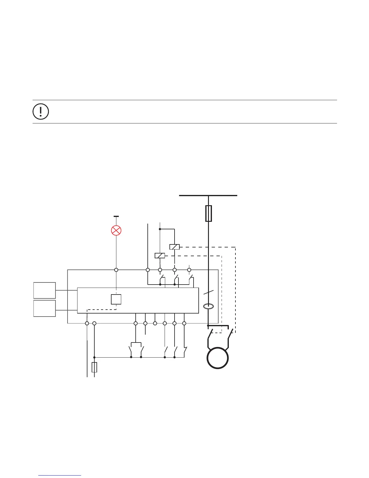
Control Function Pole-Changing Starter
Use this function in a feeder that requires a two-pole or dahlander motor to start-stop in one direction of rotation.
• Speed 1: contactor on output DO0, DI4 for start; parameter Ie1 for motor current
• Speed 2: contactor on output DO1, DI3 for start, parameter Ie2 for motor current
• Optionally DI0 can be used for contactor checkback supervision
• Optionally DI4/DI3 can be used to start the motor at speed one/two and DI5 to stop it
• Optionally DO2 or DO3 can be used as fault output
The voltage dip function is not supported in this control function
Set I
e2
according to the motor nameplate
The following diagram shows the UMC wired for two-pole operation. A signal lamp is connected to DO3 which serves as a fault out-
put. The main contactor is connected to DO0 and DO1. Two auxiliary contacts are used for contactor checkback monitoring. The
motor can be started locally via DI4 (speed one) or DI3 (speed two) and stopped via DI5. The remaining digital inputs can be freely
used.
—
Circuit diagram of the UMC for controlling a two-pole motor. The checkback contacts k81/k91 are optional
83
 Loading...