10
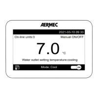
— Indicates the setpoint value currently set
— Indicates the current status of the unit. This status can be:
WAIT = Unit waiting for control board start (5 seconds);
ON = Unit active;
OFF from alarm = Unit stopped due to alarm;
Board restart = Unit waiting for start procedure (20 seconds);
OFF from BMS = Unit turned o via command incoming from BMS;
OFF from time = Unit turned o from time setting;
OFF from ID = Unit turned o via digital input (ID1);
OFF from Display = Unit turned o from pressing the key on the touch display (
);
— Indicates the current power value required by the thermostat. The power per-
centage required is represented by the green colour of the bands (each band
indicates a 10% of power)
— They indicate the current values of the following parameters:
Sv.wat.inl. = Evaporator water inlet temperature;
Sv.wat.out. = Evaporator water outlet temperature;
AP = Value read by the high pressure transducer;
BP = Value read by the low pressure transducer;
Evap. = Indicates the status of the pumps on the evaporator (green = On; grey =
O);
Cond. = Indicates the status of the pump (if installed and managed by the unit
board) on the condenser (green = On; grey = O);
Comp.1 = Compressor 1 speed percentage value;
— Enables to access the "COMPRESSORS" page (for further information refer to the
later dedicated section)
— Enables to access the "CONDENSER" page (for further information refer to the
later dedicated section)
— Enables to access the "EVAPORATOR" page (for further information refer to the
later dedicated section)
3.4 MAIN FREECOOLING MONITOR TBA/TBG
— Indicates the Freecooling input temperature
— Enables to access the "COMPRESSORS" page (for further information refer to the
later dedicated section)
— Enables to access the "CONDENSER" page (for further information refer to the
later dedicated section)
— Enables to access the "EVAPORATOR" page (for further information refer to the
later dedicated section)
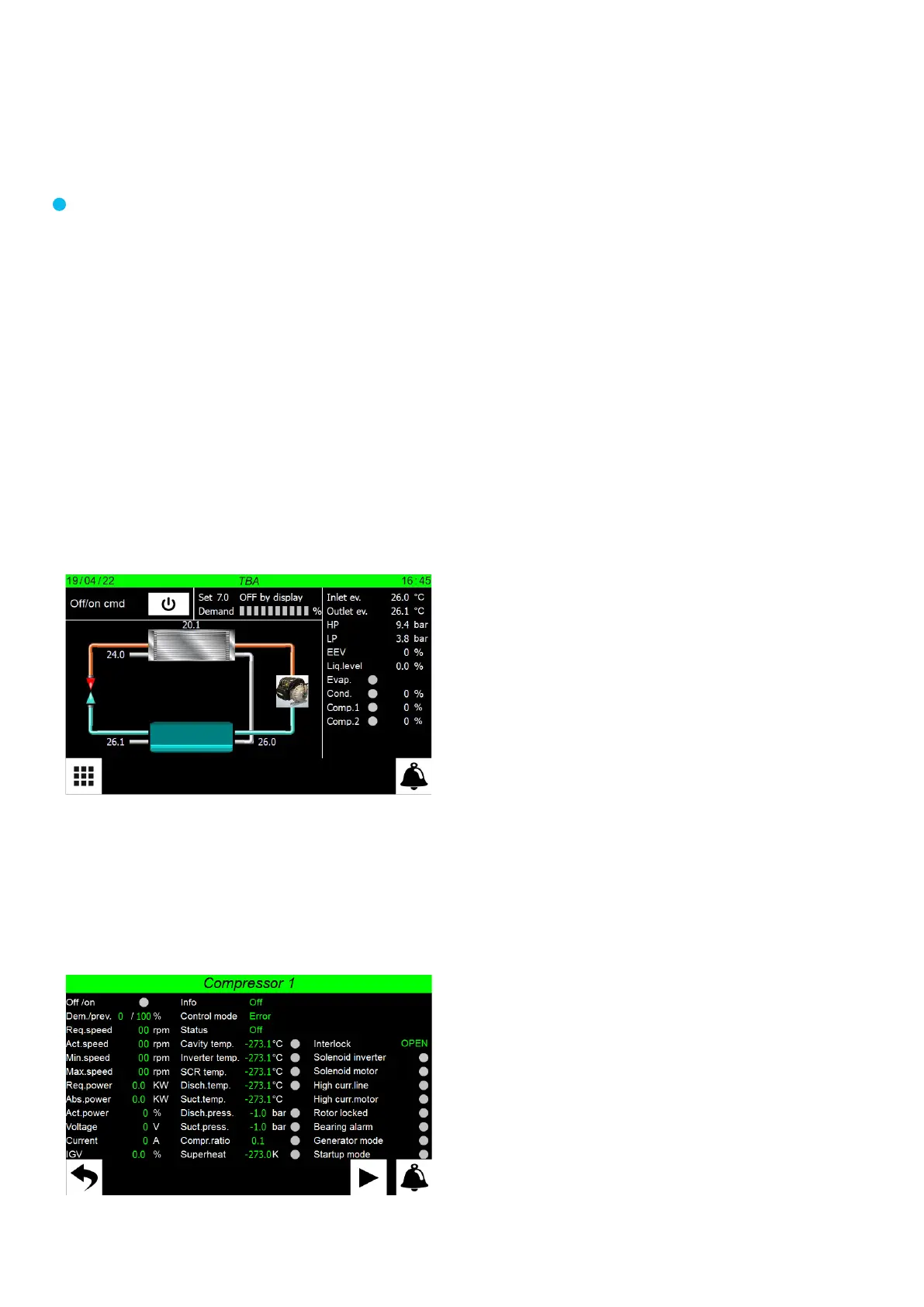
MAIN MONITOR COMPRESSORS PAGE
1. Indicates which compressor the page data refers to
2. They indicate the current values of the following parameters:
O/on = current status of the compressor (green = On; grey = O);
Req./MaxReq. = power level required by the compressor;
Sp.Req. = target speed which the compressor aims at to achieve the request;
Cur.sp.. = current compressor speed;
Min.Sp. = minimum speed value calculated by the compressor per work area;
Max.sp.. = maximum speed value calculated by the compressor per work area;
Pow.req. = power value required by the compressor;
Pow.Aabs. = current power absorbed by the compressor;
Cur.pow. = percentage of power currently supplied;
Voltage = voltage of the compressor;
Current = current absorbed by the compressor;
IGV = opening percentage of the IGV valve;
3. They indicate the current values of the following parameters:
Info = indicates the current status of the compressor, this can be:
— O: compressor o;
— On: compressor on;
— Repositioning: compressor o repositioning of the IGV valve in progress;
— Al.Turbocor: compressor in alarm;
— Lim.High TGP: Limit for pressing gas temperature;
— O stable demand: preliminary stage for switching on the new compressor,
the active compressors are required to stabilise at a set speed;
— O write speed: calculation of the target speed for the new compressor at
start-up, checking the current speeds of the active compressors;
— On start compressor: compressor ready for start-up;
— On stag. valve open: staging valve open;
— On closing stag. valve: staging valve closed;
— O time between startup: compressor o for minimum switch-o time;
Mode control = indicates the control mode; this mode can be:
— Error: the compressor signals an error condition;
— Calibration mode: compressor in calibration stage (support only);
— Manual mode: compressor active in manual mode (support only);
— Analog mode: not used;
— Modabus mode: compressor active via command of the pCO board;
— Chiller mode: not used;
Status = indicates the current status of the compressor, it can be:
— o: compressor o;
— Locked out state: situation after an alarm has ceased;
— System Resetting: the compressor is in reset stage;
— Ramping Up: the compressor is in start-up stage;
— Partially Closed Vane: the compressor is closing the IGV valve;
— Normal Operation State: the compressor is operating normally;
— Maximum Flow State: the compressor is operating at full speed;
— Minimum IGV% reached: minimum opening of the IGV valve;
— Interlock Open: the compressor is waiting for consent from the pCO board;
— Fault is Active: the compressor is stopped for alarm;
— Inverter temp. High: high temperature of the internal inverter;
— Ready for demand: the compressor is ready;
(1)
Temp. cavity = indicates the current cavity temperature;
(1)
Temp. inverter = indicates the current temperature of the internal inverter;
(1)
Temp.SCR = indicates the current temperature of the SCR;
(1)
Temp.mand. = indicates the current temperature of the pressing line;
Int.temp. = indicates the current intake temperature;
(1)
Press.mand. = indicates the current pressure of the pressing line;
(1)
Int.pres. = indicates the current intake pressure;
(1)
Compr.rat. = indicates the current value of the compression ratio;
(1)
Superheat = indicates the overheating value;
4. They indicate the current values of the following parameters:
(2)
Interlock = current status of consent to compressor operation;
(2)
Inverter solenoid = current status of the inverter solenoid;
(1)
Line high curr. = current status of the compressor power supply;
(3)
Motor high curr. = motor overcurrent control;
(3)
Rotor blocked = rotor lock control;
(3)
Bearing alarm = bearing alarm control;
(3)
Generator mode = inertial rotation control after stop;
(3)
Start mode = compressor start-up procedures control;
Key:
(1)
These signals may have one of the following states:
grey = standard size;
yellow = size in pre-alarm;
red = size in alarm;
(2)
These signals may have one of the following states:
green = load energised;
grey = load in standby;
(3)
These signals may have one of the following states:
grey = standard size;
yellow = non standard size;

 Loading...