26
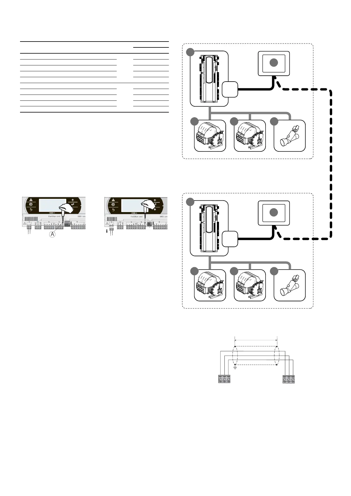
9.30 NOTES ON CONNECTING TWO MASTER/SLAVE UNITS
Table of contents Element Unit
Address
PLAN MODBUS
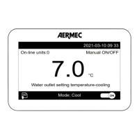
1 Display touch screen pGDTouch
Master
6
2 PCO5+ control board 1
3 EEV electronic valve driver 198
4 Driver turbocor 1 1
5 Driver turbocor 2 2
6 Display touch screen pGDTouch
Slave
7
7 PCO5+ control board 2
8 EEV electronic valve driver 198
9 Driver turbocor 1 1
10 Driver turbocor 2 2
The Master/Slave electrical connection of the two chillers is performed via a pLAN
line cable as shown in the gure (dotted line).
The pLAN address of the Master board must be set to 1 manually (default setting).
The pLAN address of the Slave board must be set to 2 manually, according to the
following procedure:
1. Using a suitable screwdriver, press the "A" key for 5 seconds. The pLAN address
will start to ash;
2. Repeatedly press the key until reaching the desired address and remove the
screwdriver;
3. Wait until the address starts ashing quickly, in this stage the address is stored
but not yet active for the application program;
4. Disconnect power from the control;
5. Return power to the control, now the address is active;
IMPORTANT 1: Provide the "evaporator common output probe" of the master and
place it in a point where the water temperature change is detected with only the
master on or with only the slave on. If a storage tank is present position it inside it.
IMPORTANT 2: In case of WMX/G and TW110 should you wish to change the mode
(COOLING/HEATING) it must be done both on the master and on the slave. The mas-
ter does NOT force change of the operating mode of the slave.
J11
J11
Plan
Modbus
Plan
Modbus
SLAVE unit
pLAN cable characteristics for MASTER/SLAVE connection:
Connect the screen to the ground

 Loading...