22
— Indicates the number of hours of operation for the various components (the
number at the top indicates the index of the component in case there are more
than one on the unit):
Pump hours sys. = system side pumps work hours number;
Ext. fan/pump hours = source side pumps work hours number;
Compressor hours = compressors work hours number;
— Indicates the number of peaks made by each compressor
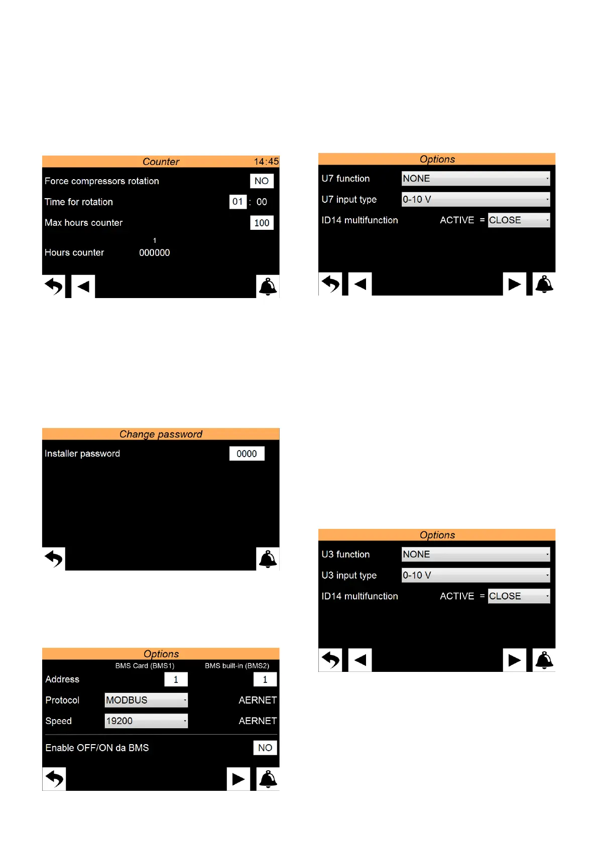
9.12 DISPLAYS THE WORK HOURS STATUS OF THE
COMPONENTS OF THE UNIT PAGE 2
— Compressor rotation forcing enabling
— Indicates the time when the rotation is carried out if the maximum hour count
has been exceeded
— Displays the elapsed hours. The count starts only if the function is enabled and
resets only if rotation is carried out with another compressor.
The hours of compressors 2/3/4 are displayed only if enabled.
9.13 SETS PASSWORD FOR INSTALLER MENU DEFAULT
0000
Enables to change the password value to access the installer menu. We recommend
that not to change the default password and, if changing it is required, to mark and
store the new password in order to ensure the possibility of access in the future.
9.14 SETTINGS RELATED TO THE BMS
— Sets the address to be assigned to the BMS1 (i.e. accessory AER485P1)
— Sets the protocol to be used for the BMS1. The available protocols are:
MODBUS;
CAREL;
LON WORKS (currently not available);
pCOweb;
— Sets the communication speed for the BMS1
— Sets the address to be assigned to the BMS2 (i.e. accessory AERNET)
— Sets whether to enable the ON/OFF command from an external BMS supervisor
9.15 TBX/WTX/WTG MULTIFUNCTION INPUT SETTINGS
— Sets the function to be assigned to the analogue input U7. The functions can be:
NONE = multifunction input not used;
POWER LIMIT = based on the signal applied to the analogue input U7, a value will
be established to be applied to the power request limit by the system;
POWER REQUEST = based on the signal applied to the analogue input U7, the
power request that the unit must meet will be established;
SETPOINT = based on the signal applied to the analogue input U7, the value of the
setpoint to be applied to the unit will be established;
— Sets the type of signal applied to the analogue input U7. The signals managed
can be:
0-10V = signal in 0-10V voltage;
4-20mA = signals in 4-20mA current;
NTC = signal from NTC temperature probe;
— To enable the U7 multifunction input, it is required to operate on the digital
input ID14. It is possible to choose the state with which to enable use of the
multifunctional input:
CLOSED = if ID14 is closed the U7 input open;
OPEN = if ID14 is open the U7 input enabled;
9.16 TW110/WMX/WMG MULTIFUNCTION INPUT SETTINGS
— Sets the function to be assigned to the analogue input U3. The functions can be:
NONE = multifunction input not used;
POWER LIMIT = based on the signal applied to the analogue input U3, a value will
be established to be applied to the power request limit by the system;
POWER REQUEST = based on the signal applied to the analogue input U3, the
power request that the unit must meet will be established;
SETPOINT = based on the signal applied to the analogue input U3, the value of the
setpoint to be applied to the unit will be established;
— Sets the type of signal applied to the analogue input U3. The signals managed
can be:
0-10V = signal in 0-10V voltage;
4-20mA = signals in 4-20mA current;

 Loading...