9
3 MAIN MONITOR
This page contains general information on the current status and operation of the
unit. Moreover, by pressing the graphical elements that represent the components
of the cooling circuit, it is possible to enter specic sub-windows where to view the
data relating to the selected component;
ATTENTION: certain information is only visible if it is available on the unit
(for example data relating to the Free-cooling circuit).
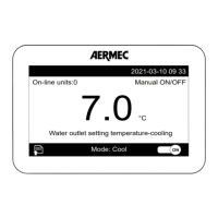
3.1 MAIN MONITOR TBX/TBA/TBG
— Indicates today’s date set on the system
— Indicates the current date set on the system
— Indicates the setpoint value currently set
— Indicates the current status of the unit. This status can be:
WAIT = Unit waiting for control board start (5 seconds);
ON = Unit active;
OFF from alarm = Unit stopped due to alarm;
Board restart = Unit waiting for start procedure (20 seconds);
OFF from BMS = Unit turned o via command incoming from BMS;
OFF from time = Unit turned o from time setting;
OFF from ID = Unit turned o via digital input (ID1);
OFF from Display = Unit turned o from pressing the key on the touch display (
);
— Indicates the current power value required by the thermostat. The power per-
centage required is represented by the green colour of the bands (each band
indicates a 10% of power)
— They indicate the current values of the following parameters:
Sv.wat.inl. = Evaporator water inlet temperature;
Sv.wat.out. = Evaporator water outlet temperature;
AP = Value read by the high pressure transducer;
BP = Value read by the low pressure transducer;
EVV = Current opening value (percentage) of the electronic valve;
Liq. level. = level of liquid inside the attached heat exchanger;
Evap. = Indicates the status of the pump on the evaporator (green = On; grey =
O);
Cond. = Indicates the fan status (green = On; grey = O), also indicates the fan
speed as a percentage;
Comp.1 = Value of revs for compressor 1;
Comp.2 = Value of revs for compressor 2;
— Enables to access the "COMPRESSORS" page (for further information refer to the
later dedicated section)
— Enables to access the "ELECTRONIC VALVE" page (this page is not available on
some units. For further information refer to the later dedicated section)
— Enables to access the "CONDENSER" page (for further information refer to the
later dedicated section)
— Enables to access the "EVAPORATOR" page (for further information refer to the
later dedicated section)
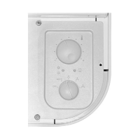
3.2 MAIN MONITOR WTX/WTG
— Indicates today’s date set on the system
— Indicates the current date set on the system
— Indicates the setpoint value currently set
— Indicates the current status of the unit. This status can be:
WAIT = Unit waiting for control board start (5 seconds);
ON = Unit active;
OFF from alarm = Unit stopped due to alarm;
Board restart = Unit waiting for start procedure (20 seconds);
OFF from BMS = Unit turned o via command incoming from BMS;
OFF from time = Unit turned o from time setting;
OFF from ID = Unit turned o via digital input (ID1);
OFF from Display = Unit turned o from pressing the key on the touch display (
);
— Indicates the current power value required by the thermostat. The power per-
centage required is represented by the green colour of the bands (each band
indicates a 10% of power)
— They indicate the current values of the following parameters:
Sv.wat.inl. = Evaporator water inlet temperature;
Sv.wat.out. = Evaporator water outlet temperature;
AP = Value read by the high pressure transducer;
BP = Value read by the low pressure transducer;
EVV = Current opening value (percentage) of the electronic valve;
Liq. level. = level of liquid inside the attached heat exchanger;
Evap. = Indicates the status of the pumps, where (1) indicates the primary one and
(2) the reserve one, on the evaporator (green = On; grey = O);
Cond. = Indicates the status of the pump (if installed and managed by the unit
board) on the condenser (green = On; grey = O);
Comp.1 = Compressor 1 speed percentage value;
Comp.2 = Compressor 2 speed percentage value;
Comp.3 = Compressor 3 speed percentage value;
Comp.4 = Compressor 4 speed percentage value;
— Enables to access the "COMPRESSORS" page (for further information refer to the
later dedicated section)
— Enables to access the "ELECTRONIC VALVE" page (this page is not available on
some units. For further information refer to the later dedicated section)
— Enables to access the "CONDENSER" page (for further information refer to the
later dedicated section)
— Enables to access the "EVAPORATOR" page (for further information refer to the
later dedicated section)
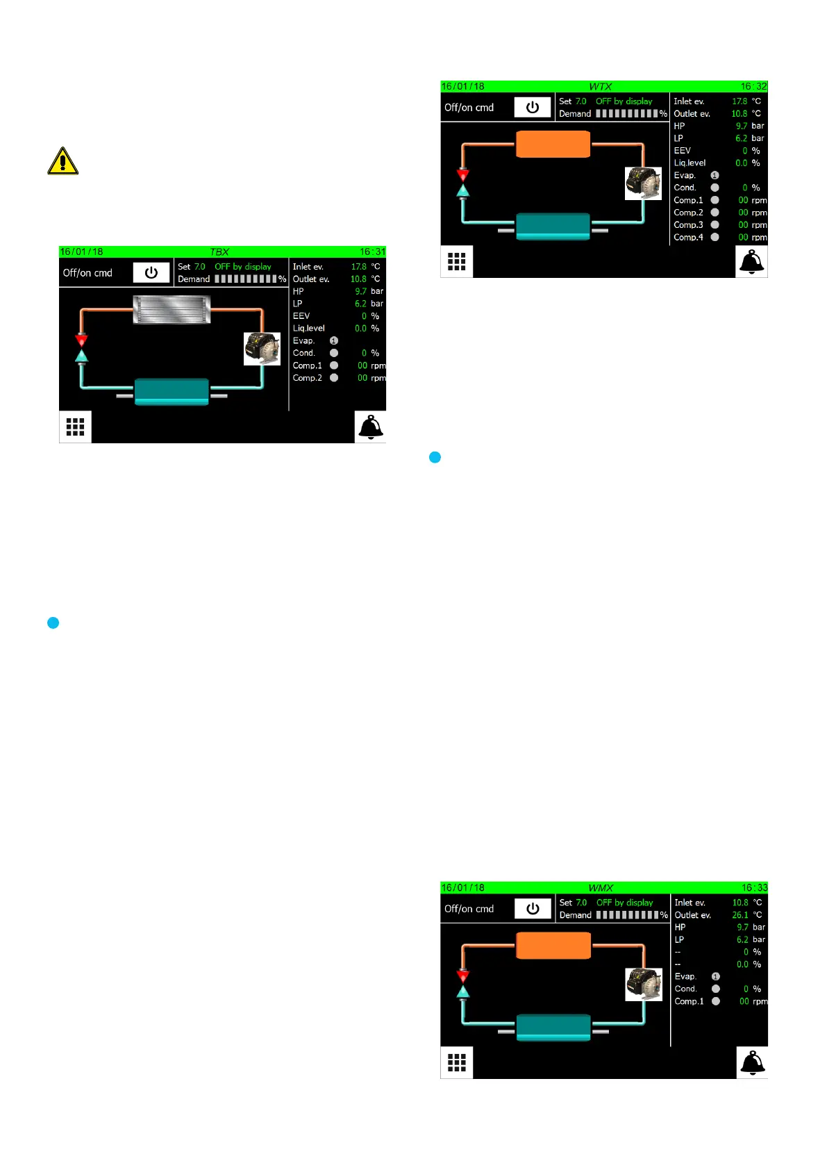
3.3 MAIN MONITOR WMX/WMG/TW110
— Indicates today’s date set on the system
— Indicates the current date set on the system

 Loading...