To Replace the Power-Line Fuse
The power-line fuse is located within the function generator’s fuse-holder
assembly on the rear panel (see page 22). The function generator is shipped
from the factory with a 500 mAT slow-blow fuse installed (part number
2110-0458). This is the correct fuse for all line voltages.
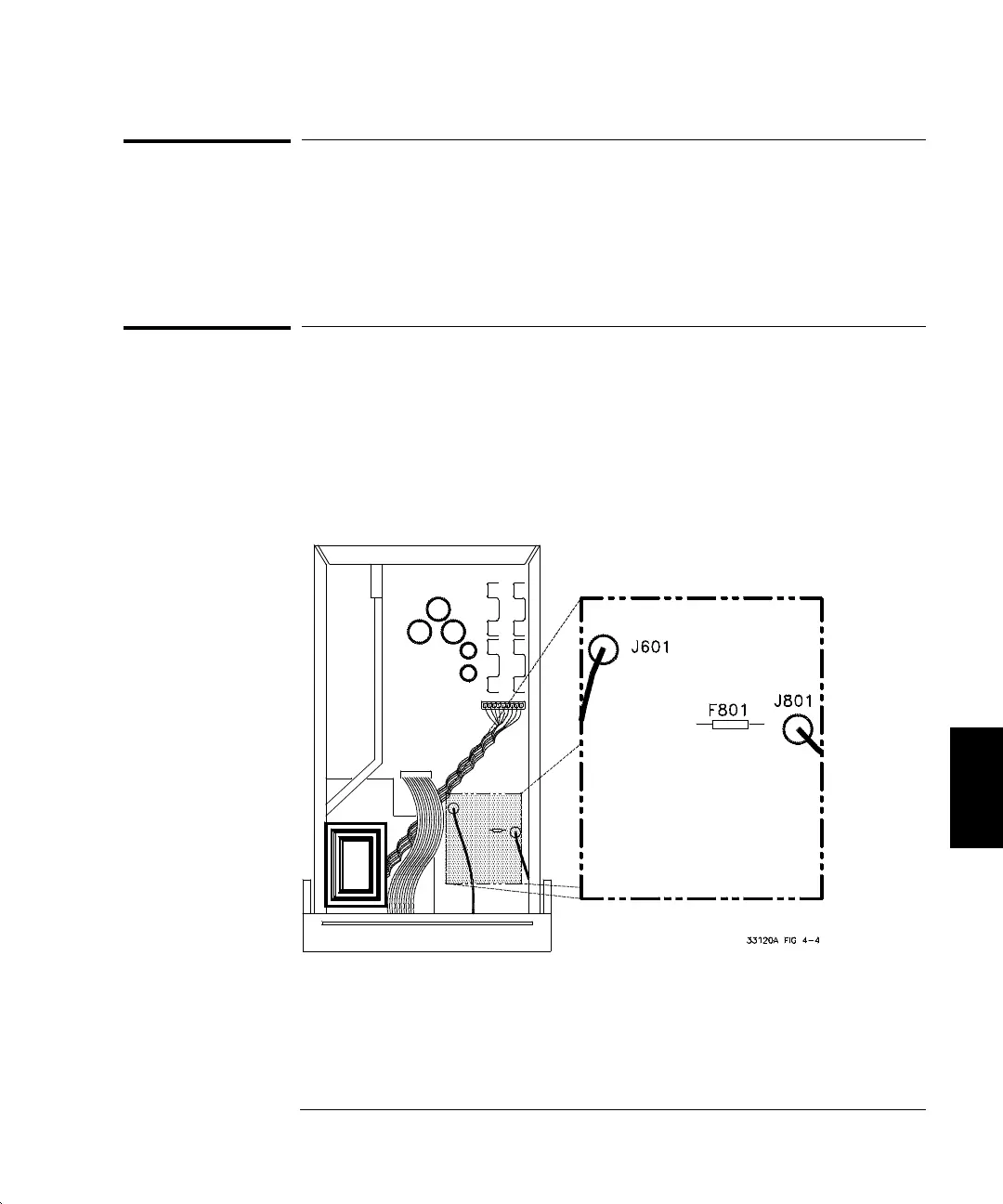
To Replace the Output Protection Fuse (F801)
The Output Protection Fuse is located inside the function generator.
This fuse is a thru-hole soldered 500 mA part (part number 2110-0716).
The fuse is located near the output connector (J801) on the main PC board.
You will need to disassemble the function generator to replace this fuse
(use a
TORX T-15 driver to remove the screws located on the rear panel).
The disassembly procedure is shown on page 130.
6
Chapter 6 Service
To Replace the Power-Line Fuse
107

 Loading...


