Filters
Block 5 on block diagram page 129; Schematic on page 135.
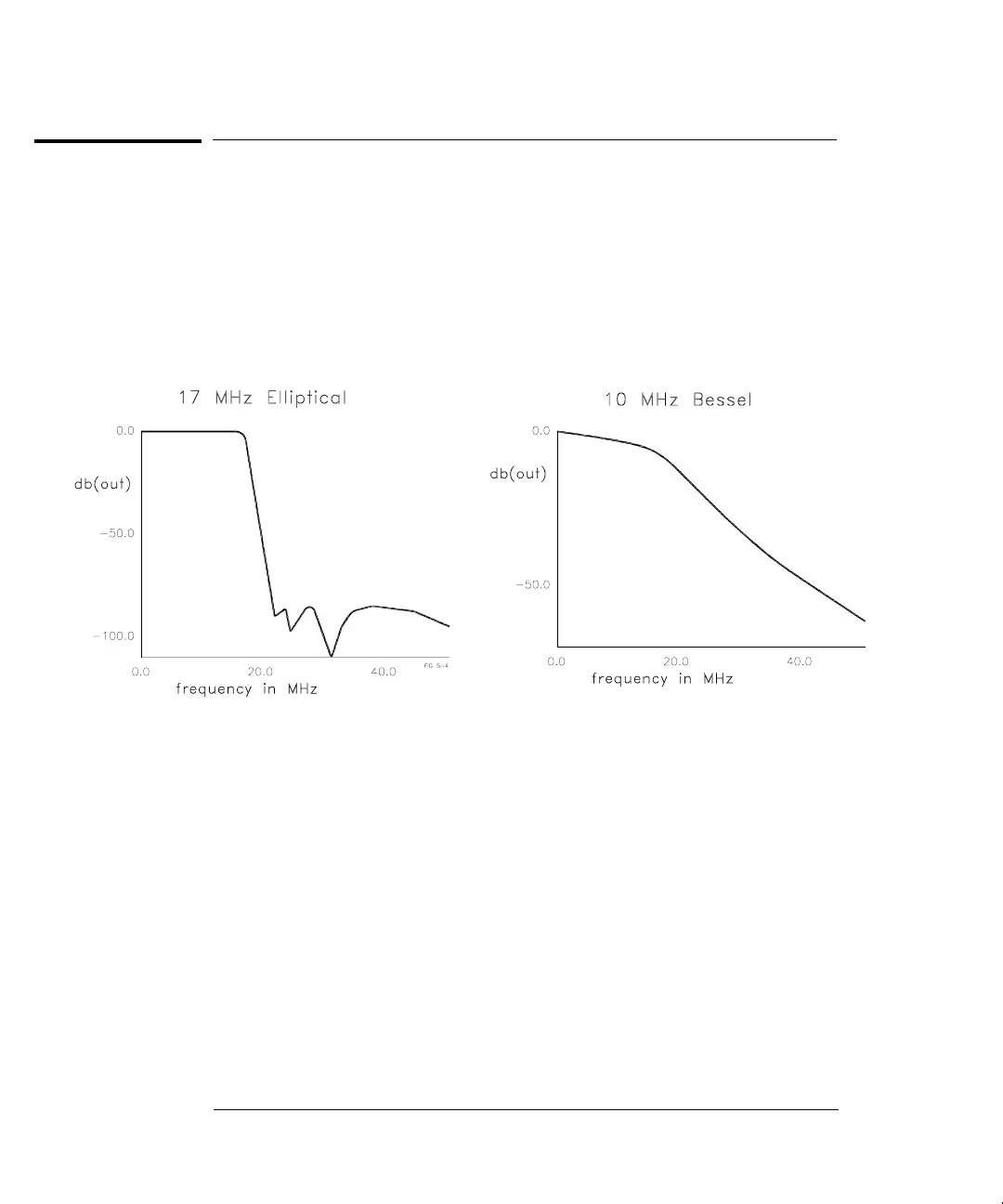
The output of the Waveform DAC passes through one of two anti-alias
filters. A 17 MHz 9th order elliptical filter is used for the sine wave and
square wave output functions. A 10 MHz 7th order Bessel filter is used
for filtering all other output functions, including all arbitrary waveshapes.
The diagrams below show the typical frequency response of these filters.
The filters are switched in or out of the signal path by latching relays
K501 and K502. Their set or reset state is selected by momentarily
pulsing the appropriate coil of the relay. Relay coils are pulsed with
5 volts for 15 ms through relay drivers U301 and U302. The main
controller, U102, writes data bytes to ASIC U103 which transmits this data
to the relay drivers via the internal 3-wire serial data bus (SERCLK,
SERDAT, and SERSTB) to accomplish these relay state changes. When
K501 and K502 are set, the 10 MHz Bessel filter is selected.
Chapter 5 Theory of Operation
Filters
92

 Loading...


