Output Amplifier Adjustment (Optional)
This adjustment procedure should only be performed following repairs to
the Output Amplifier circuitry. The adjustment improves the high frequency
performance of the Output Amplifier.
1 Remove the function generator power and cover as described on page 130.
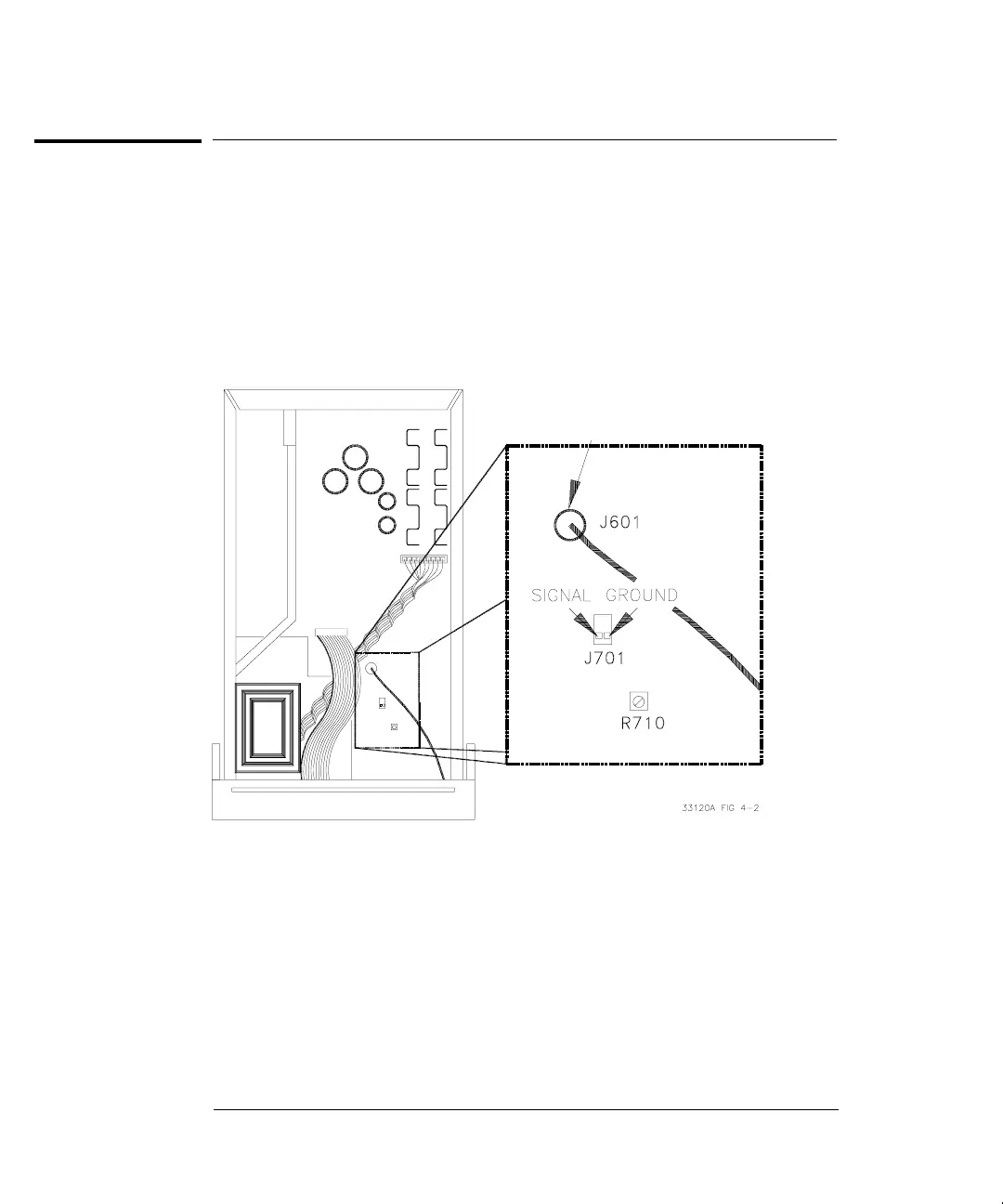
2 Use a DMM to measure the ACrms voltage across J701 as shown below.
3 Turn on the function generator.
4 Set the function generator for a 1 kHz, 1V rms, sine wave output.
5 Adjust R710 for a minimum reading on the voltmeter. Typical readings
are less than 0.005 Vrms.
6 Replace the covers as described on page 130.
Cable Shield is
Circuit Ground
Chapter 4 Calibration Procedures
Output Amplifier Adjustment (Optional)
80

 Loading...


