5-32
Making Measurements
To make cursor measurements
To make cursor measurements
The following steps guide you through the front-panel Cursors key. You can use
the cursors to make custom voltage or time measurements on the signal.
1 Connect a signal to the oscilloscope and obtain a stable display.
2Press the
Cursors key, then press the Mode softkey.
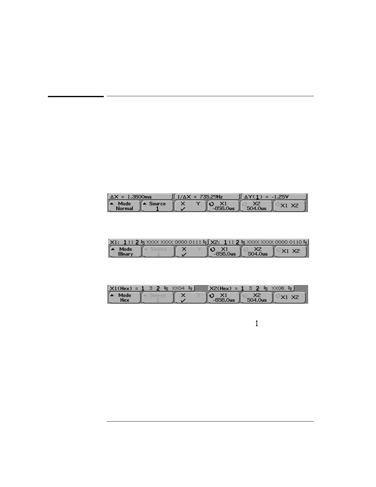
X and Y cursor information is displayed on the softkeys. ∆X, 1/∆X, ∆Y, and
binary and hexadecimal values are displayed on the line above the softkeys. The
three cursors modes are:
Normal ∆X, 1/∆X, and ∆Y values are displayed. ∆X is the difference between
the X1 and X2 cursors and ∆Y is the difference between the Y1 and Y2 cursors.
Binary Binary logic levels are displayed directly above the softkeys for the
current X1 and X2 cursor positions for all displayed channels.
Hex Hexadecimal logic levels are displayed directly above the softkeys for the
current X1 and X2 cursor positions for all displayed channels.
In hexadecimal and binary mode, a level can display as 1 (higher than trigger
level), 0 (lower than trigger level), indeterminate state ( ), or X (don’t care).
In binary mode, X is displayed if the channel is turned off. In hex mode, the
channel is interpreted as a 0 if turned off.
 Loading...


