Digital Channels 6
Agilent InfiniiVision 3000 X-Series Oscilloscopes User's Guide 119
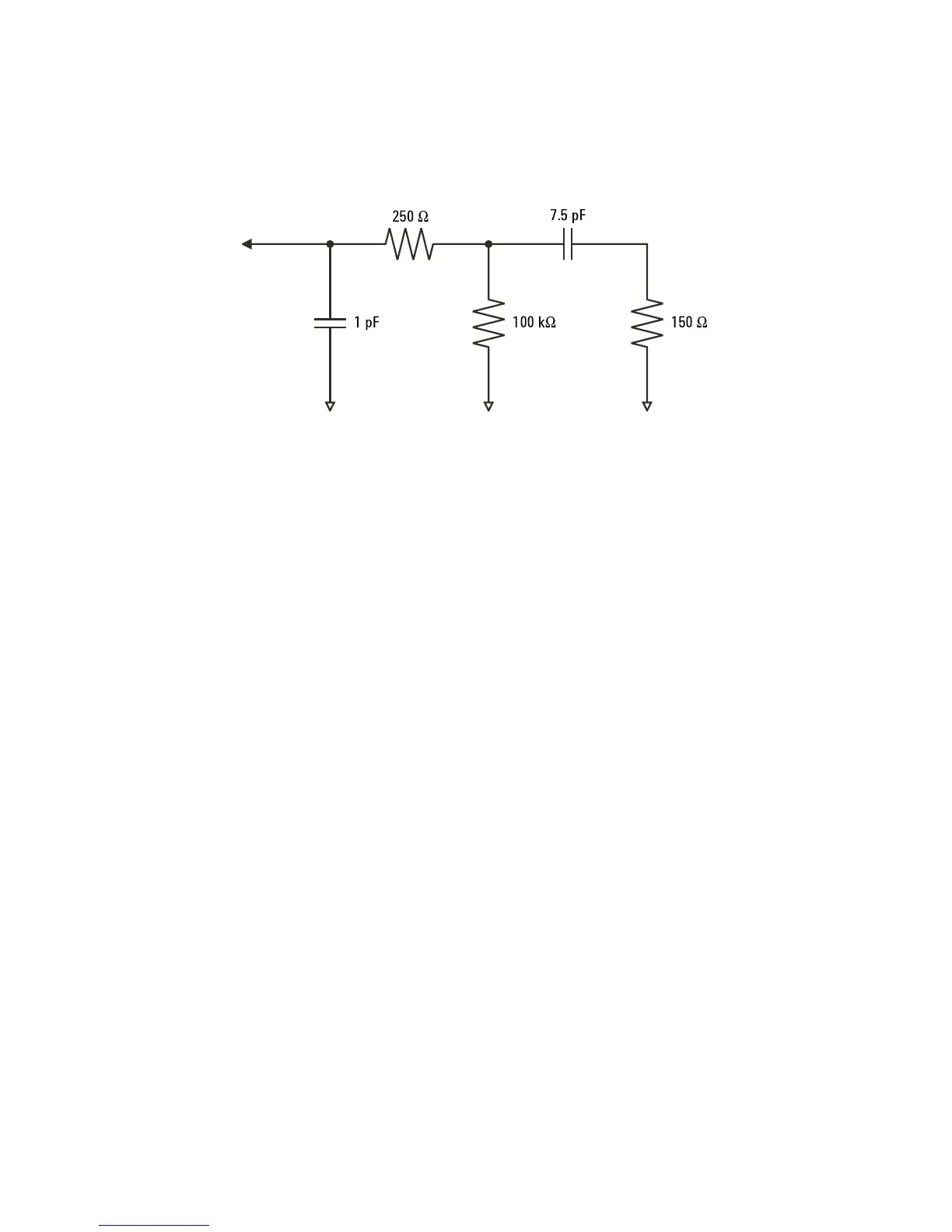
The impedance plots for the two models are shown in these figures. By
comparing the two plots, you can see that both the series tip resistor and
the cable's characteristic impedance extend the input impedance
significantly. The stray tip capacitance, which is generally small (1 pF),
sets the final break point on the impedance chart.
Figure 22 High-Frequency Probe Equivalent Circuit

 Loading...


