118 Agilent InfiniiVision 3000 X-Series Oscilloscopes User's Guide
6 Digital Channels
Input Impedance
The logic probes are passive probes, which offer high input impedance and
high bandwidths. They usually provide some attenuation of the signal to
the oscilloscope, typically 20 dB.
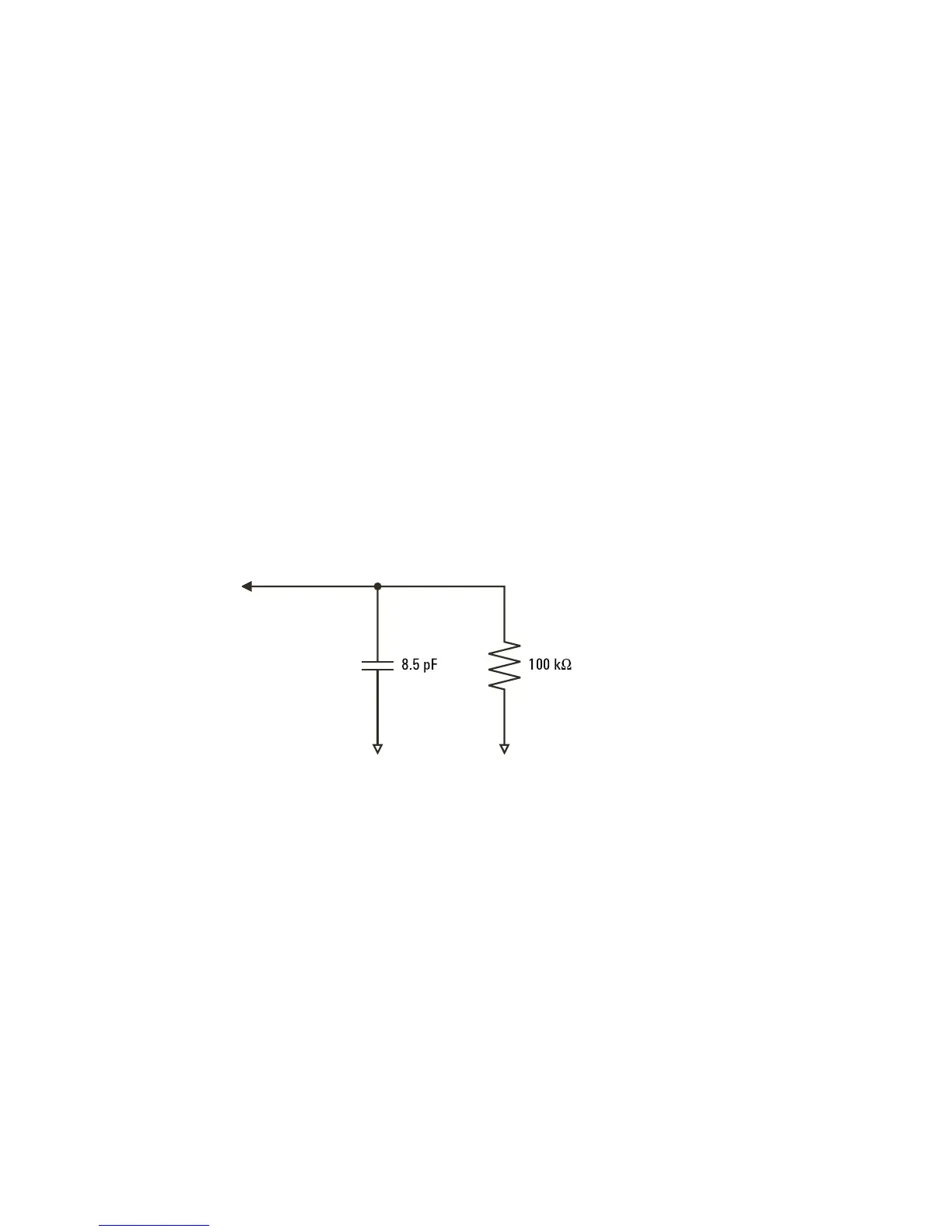
Passive probe input impedance is generally specified in terms of a parallel
capacitance and resistance. The resistance is the sum of the tip resistor
value and the input resistance of the test instrument (see the following
figure). The capacitance is the series combination of the tip compensating
capacitor and the cable, plus instrument capacitance in parallel with the
stray tip capacitance to ground. While this results in an input impedance
specification that is an accurate model for DC and low frequencies, the
high-frequency model of the probe input is more useful (see the following
figure). This high- frequency model takes into account pure tip capacitance
to ground as well as series tip resistance, and the cable's characteristic
impedance (Z
o
).
Figure 21 DC and Low-Frequency Probe Equivalent Circuit

 Loading...


