1-4 i3070 Series 5i Help
Getting Started
System Hardware
• Testhead
The two- module testhead contains the hardware resources required to
execute tests. Each module in the testhead holds the following cards:
• A Mother Card
• A Module Control Card
• An ASRU Card
• Up to nine pin cards
•Test Fixture
The test fixture is the hardware interface between the testhead and the
board or device under test (DUT).
• Controller
The controller is the computer that controls the test system. The
controller pod also houses the System Card and DUT power supplies.
•System Card
The System Card System card is the conduit for communication
between the testhead modules and controller. It provides the means to
detect and respond to safety events, actuate fixture vacuum and
pull- down towers, and actuate auxiliary connection relays.
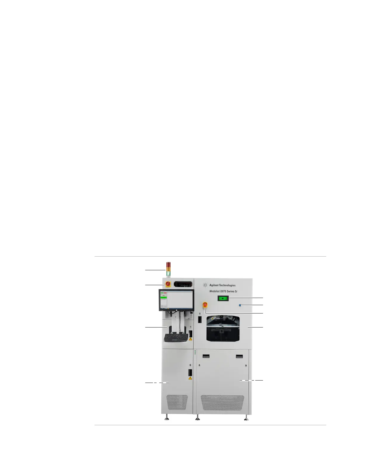
Figure 1-1 Medalist i3070 Series 5i (Left-to-Right System)
Emergency Stop Switch
Main Power Switch
Tes th ea d Po d
LCD Touch Panel
Controller Pod
Tower Light
Reset Button
Zone 2 DoorZone 1 Door

 Loading...