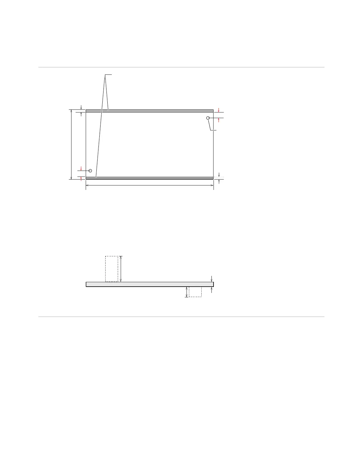
Minimum clearance
3.0 mm (0.12”)
Tooling Holes
• Use diagonally opposing holes
•
Diameter:
2.54 to 4.45 mm (0.100 to 0.175 in)
Recommended 3.175 mm (0.125 in)
Tooling Pins
Tooling pin bushing must not be located
in or lean into free area of board edge
Free Area at Board Edges
• No probing allowed in this area.
•
Components must not be located in
or lean into this area.
Board Length
Minimum: 50.0 mm (2.36 in)
Maximum: 350.0 mm (13.8 in) without top side
and dual stage probes
Board Width
Minimum: 60.0 mm (2.36 in)
Maximum: 350.0 mm (13.8 in) without top side
and dual stage probes
To l e r a n ce : 0.25 mm (0.01 in)
Length
Width
Minimum clearance
3.0 mm (0.12 in)
PCB
Nominal Board Thickness
Minimum: 0.60 mm (0.023 in)
Maximum: 4.00 mm (0.157 in)
Top Side Components
Maximum: 90.0 mm (3.54 in)
Bottom Side Components
Maximum: 30 mm (1.18 in)
PCB

 Loading...