Making Measurements 2
Testing for Continuity
U1231A/U1232A/U1233A User’s Guide 41
Testing for Continuity
Set up your multimeter to test for continuity as shown in
Figure 2- 11. Probe the test points and read the display.
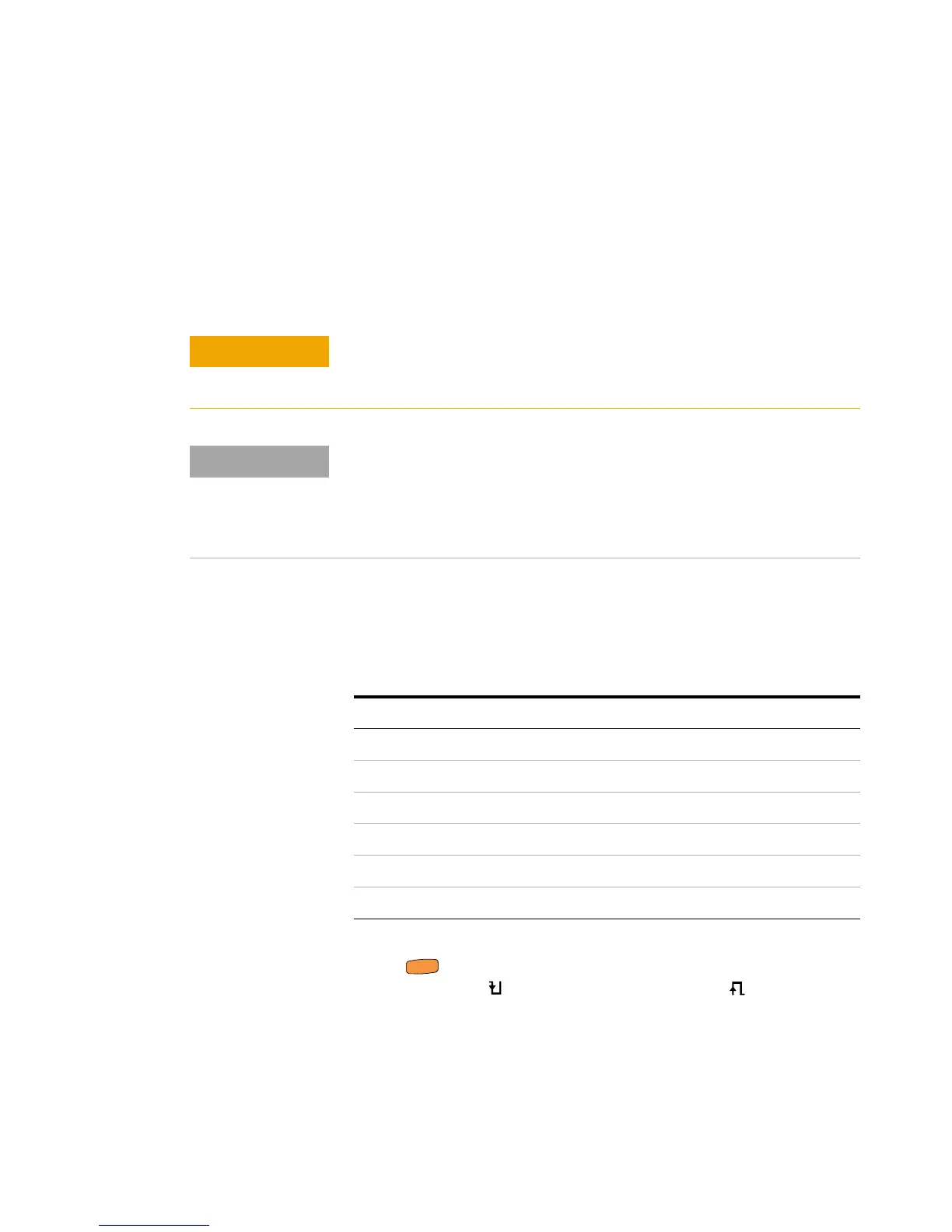
In continuity, a short means a measured value is less that
the threshold resistance values listed in Table 2- 1.
Press to switch between resistance measurement, short
continuity test ( ), or open continuity test ( ). See
Figure 2- 10 to learn more.
To avoid possible damage to your multimeter or to the equipment under
test, disconnect the circuit power and discharge all high-voltage
capacitors before testing for continuity.
Continuity is the presence of a complete path for current flow. The
continuity test features a beeper that sounds and a backlight that flashes
as long as a circuit is complete if short continuity is selected (or broken if
open continuity is selected). The audible and visual alert allows you to
perform quick continuity tests without having to watch the display.
Tab le 2- 1 Threshold resistance values
Measuring range Threshold resistance
600.0 Ω <23 ±10 Ω
6.000 kΩ <230 ±100 Ω
60.00 kΩ <2.3 ± 1 kΩ
600.0 kΩ <23 ± 10 kΩ
6.000 MΩ <131 ± 60 kΩ
60.00 MΩ <131 ± 60 kΩ

 Loading...


