134 Agilent U1251A/U1252A User’s and Service Guide
7 Performance Tests and Calibration
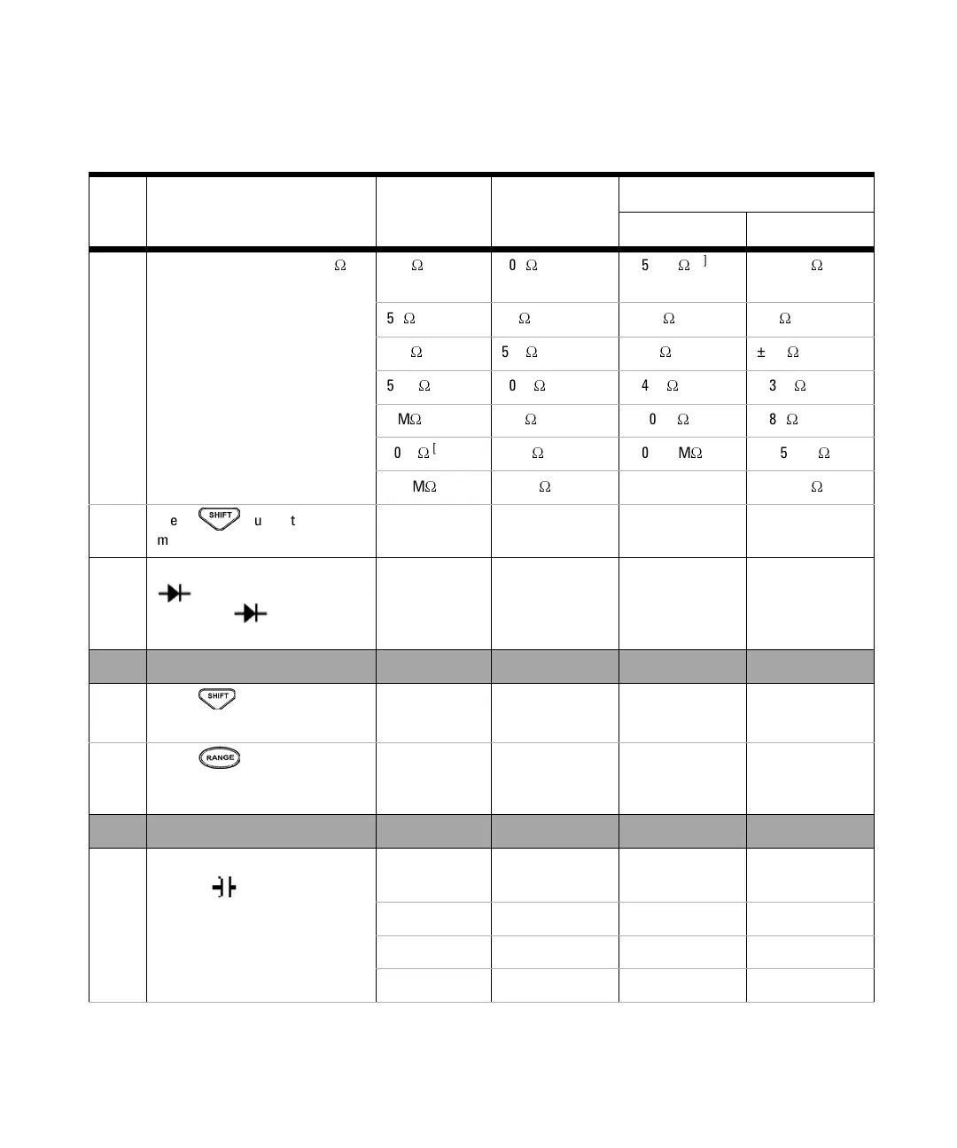
Step Test Function Range 5520A Output
Error from nominal 1 year
U1251A U1252A
8 Turn the rotary switch to the
W
position
500
W
500
W
± 500 m
W
[3]
± 350 m
W
[3]
5 k
W
5 k
W
± 4.5
W
[3]
± 3
W
[3]
50 k
W
50 k
W
± 45
W
± 30
W
500 k
W
500 k
W
± 450
W
± 300
W
5 M
W
5 M
W
± 10.5 k
W
± 8 k
W
50 M
W
[4]
50 M
W
± 0.510 M
W
± 0.505 M
W
500 M
W
500 M
W
N/A ± 40.1 M
W
9 Press button to go to ns
mode
500 nS
[5]
50 nS ± 0.7 nS ± 0.6 nS
10 Turn the rotary switch to the Hz/
position (for model
U1252A), to position (for
model U1251A)
Diode 1 V ± 1 mV ± 1 mV
33250A Output
11 Press button to go to
frequency counter mode
[6]
999.99 kHz 200 mVrms,
100 kHz
N/A ± 52 Hz
12 Press button to go to
frequency counter mode divide by
100
99.999 MHz 600 mVrms,
10 MHz
N/A ± 5.2 kHz
5520A Output
13 Turn the rotary switch to the
TEMP/ position
[7]
10.000 nF 10.000 nF ± 0.108 nF ± 0.108 nF
100.00 nF 100.00 nF ± 1.05 nF ± 1.05 nF
1000.0 nF 1000.0 nF ± 10.5 nF ± 10.5 nF
10.000 μF 10.000 μF ± 0.105 μF ± 0.105 μF