Allen & Heath 16 XB-14 User Guide
OO +6
AUX
PRE
LR
PAN
=
SIGNAL
PFL
M1
PEAK
PGM
FDR
MIX B
BUS
0
5
10
15
20
30
40
50
OO
REM MUTE
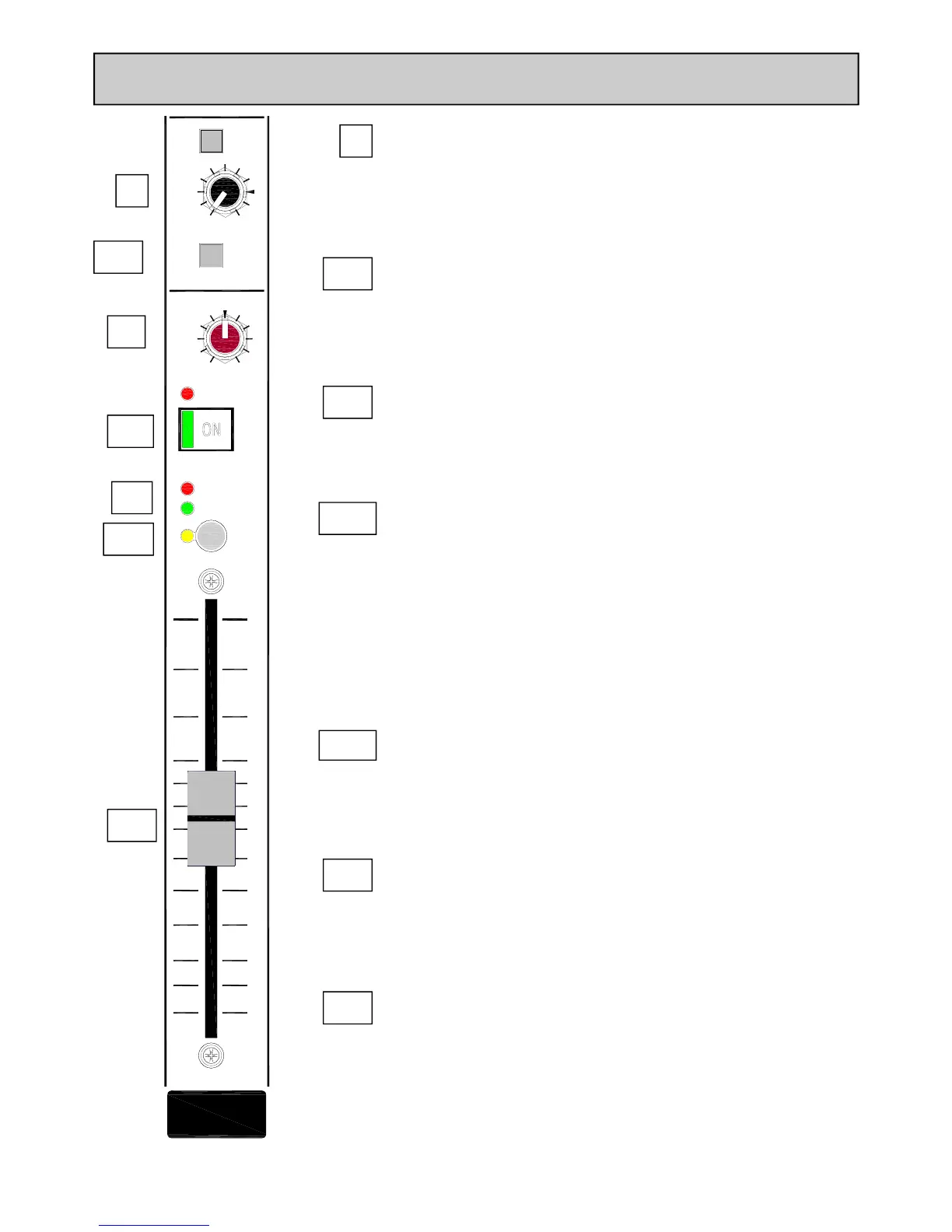
MONO INPUT CHANNEL
11
9
Aux
This control sends a signal to an auxiliary bus. The signal is sourced pre-fade
or post-fade depending on the PRE switch position. The pre-fade source
selection will be affected by the channel ON/OFF switch if active. The send
control varies the signal level to the bus from off (fully attenuated) to +6dB,
with unity gain at the arrow.
10
MIX B
The MIX B switch routes the channel signal to a stereo bus which is inde-
pendent of the main PGM (program) bus. The signal is post-fade and follows
the PAN control. The MIX B bus can be used for creating mixes for re-
cording or clean-feed sources for external equipment.
12
PAN
The pan control adjusts how the signal from the mono input channel is
shared between the left and right sides of the PGM bus and the MIX B bus.
Set to the mid position, equal amounts of signal are fed to left and right,
with pan set to L, none is sent to the Right bus.
13
SIGNAL & PEAK LEDs
The Signal LED illuminates when the pre-fader signal level is above –15dB.
The Peak LED illuminates and stays on for around 0.5 seconds when a peak
level is detected (pre-fader signal) within 5dB of clipping.
14
ON Switch
This mechanically latching switch operates the channel mute circuitry, turn-
ing the signal to the PGM, MIX B and Aux buses on or off.
The switch is illuminated green when pressed.
There is an option to disable the switch (make permanently ON) using the
option switches on the rear-panel. If this is activated, then the switch will be
illuminated green regardless of whether it is pressed or not.
There is also a remote mute option wired to a D type connector on the
rear panel. When this is wired and operated the REM MUTE red LED illumi-
nates and the mute circuit is activated regardless of whether the ON switch
is pressed.
Fader
The 100mm fader controls the level of the channel signal to the left & right
PGM bus, MIX B bus and post fade Aux.
The Mono channel faders have Fader Start switching logic available to either
interface to external equipment or activate the muting circuit for the con-
trol room speaker outputs.
9
10
11
12
13
14
PFL Switch
The PFL (Pre-Fade Listen) switch sends the channel signal to the PFL bus
and subsequently to the headphones/CRM speakers and the main L R me-
ters. Used for checking the audio signal before raising the fader or un-
muting the channel or raising the fader.
15
15
 Loading...