Allen & Heath 17 XB-14 User Guide
TELCO CHANNELS 1&2
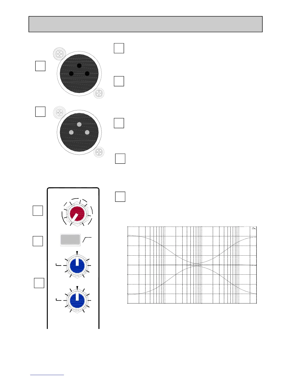
TELCO Input Gain
The Telephone Communication channel input gain control. Varies
the gain applied to the TELCO input channel from –10dB to +26dB.
TEL IN
The Telephone Communication channel input XLR socket. Wired
as Pin 1=Chassis, Pin 2=hot (+), Pin 3=Cold (-).
1
2
CLF OUT
Standard XLR output connector for the Clean-Feed output from
the Telephone Communication channel.
Wired Pin 1=Chassis, Pin 2=hot (+), Pin 3=Cold (impedance bal-
anced ground).
3
4
5
100Hz High Pass filter
Similar to the mono input channel, a 12dB per octave 2-pole high
pass filter used to filter out any low frequency rumble or pops on
the TELCO channel input.
TELCO Channel EQ
The TELCO Channel EQ is 2 band with corner frequencies of
12kHz for the HF and 80Hz for the LF.
10.00 Hz 100.00 1000.00 10000.00 30000.00
-20.00
-15.00
-10.00
-5.00
0.00
5.00
10.00
15.00
20.00
dBr
2
4
1
5
3
100Hz
-15 +15
HF
-15 +15
80Hz
LF
CLF OUT
TELCO 1
TEL IN
-1O
26
-5
5
10
20
0
12kHz
GAIN
T1
 Loading...