Rockwell Automation Publication 1734-UM013N-EN-P - September 2017 167
Indicators Appendix A
Network Status
Configuration Lock
Power
1734-IE4S Sensor Power
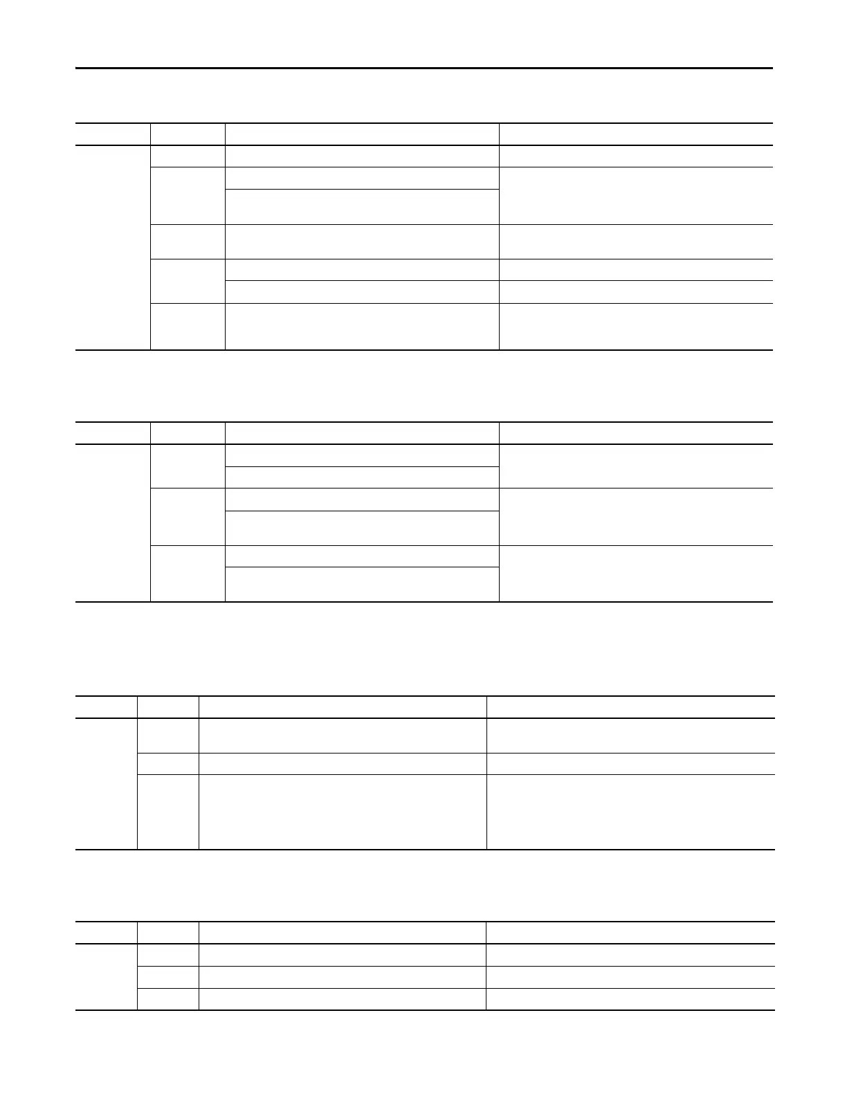
Indicator Description Recommended Action
NS Off The module is not online with the network or there is no power. Verify that your network is working properly.
Flashing green Module online with no connections in established state. Verify your network and module configuration.
The module identified the communication rate of the network but no
connections are established.
Solid green Module online with connections in established state. The module is
operating normally.
None.
Flashing red One or more I/O connections are in timed-out state. Verify your network and module configuration.
A user-initiated firmware update is in progress. Wait for firmware update to complete.
Solid red Critical link failure. The module detected an error that prevents it
from communicating on the network, such as a duplicate node
address.
Cycle power to the module. Check node addressing.
Indicator Description Recommended Action
LK
(1)
Off No configuration or configured by a GuardLogix® originator. Validate configuration by a network configuration tool, such as
RSNetWorx™ software.
Invalid configuration data.
Solid yellow Locked. None.
Valid configuration, locked by a network configuration tool, such as
RSNetWorx software.
Flashing yellow Not locked. None.
Valid configuration by a network configuration tool, such as
RSNetWorx software.
(1) Not applicable when used with GuardLogix controllers.
Indicator Description Recommended Action
PWR Off No field power applied (all modules) or severe 24VDC power over voltage
condition (1734-OBV2S only)
Apply field power that is within specification.
Green Normal condition, field power supplied and within specification. None.
Yellow Field power out of specification. Field power supplied is outside specification (all modules) or the module
is configured to use sensor power, and either the sensor is drawing too
much current (short in the wiring or sensor), or the sensor is not drawing
any current (broken wire or sensor) (1734-IE4S only).
Check your connectors, wiring, and voltages.
Indicator Description Recommended Action
S0…S3 Off Sensor power is not used. None.
Green Sensor power is used. None.
Red Over-current or under-current sensor power fault. Check connectors, wiring, and power supply.
 Loading...


