34 Rockwell Automation Publication 1734-UM013N-EN-P - September 2017
Chapter 2 Safety Inputs, Safety Outputs and Safety Data
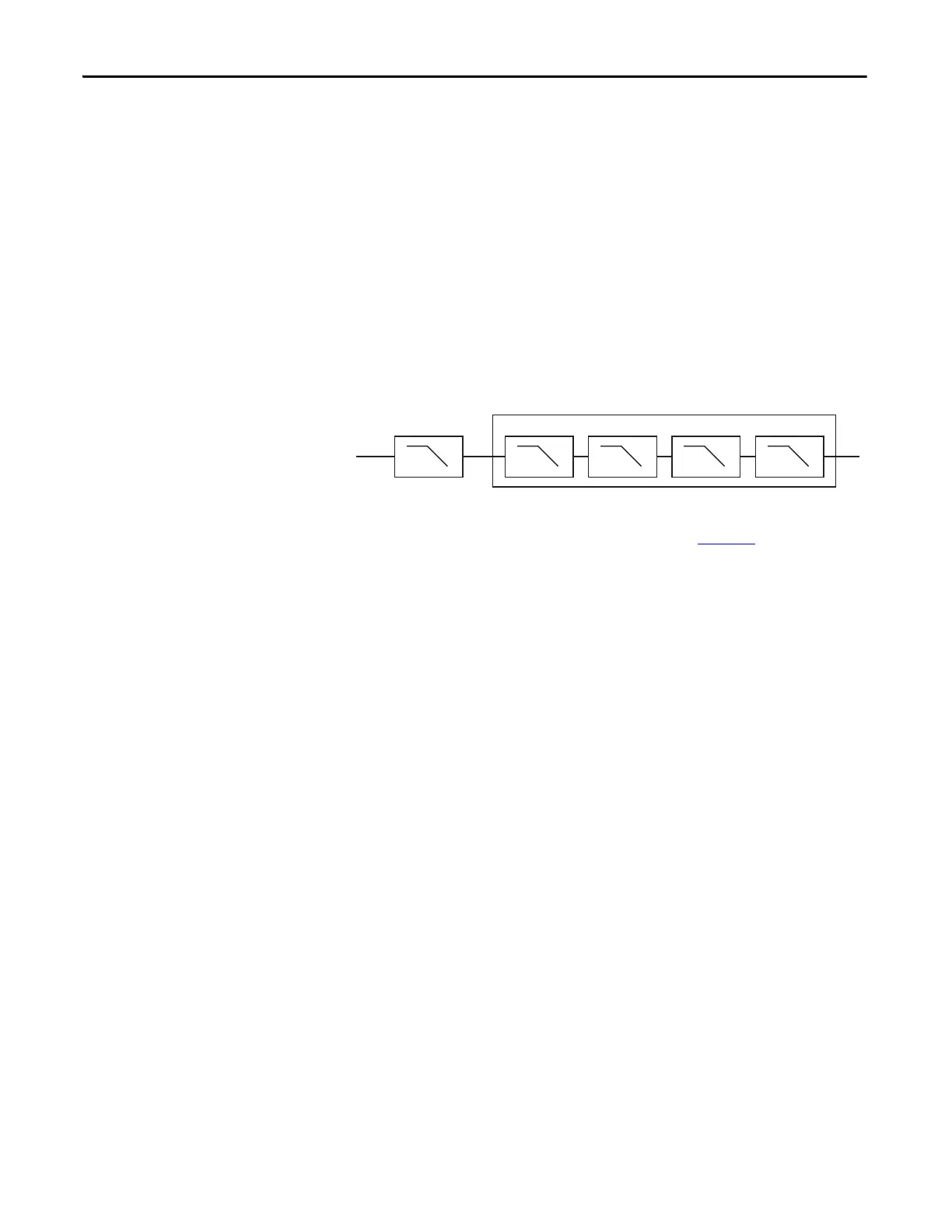
Digital Input Filter
A single-pole, anti-aliasing filter of 10 Hz is followed by a four-pole digital filter.
Choose from the following available corner frequencies.
• 1 Hz
• 5 Hz
• 10 Hz
• 50 Hz
The default input filter setting is 1 Hz.
Figure 12 - Filter Operation
The filter setting affects the step response of the module. See the technical
specifications for the 1734-IE4S module, that start on page 174
.
For the analog input modes, the input filter settings set the low-pass filter to filter
out noise that can be present on the signal. In Tachometer mode, the input filter
removes noise that can be present on the calculated frequency, effectively
changing how rapidly the tachometer frequency changes to provide a value with
less jitter.
Sensor Power Supply
You can configure the module to supply power to the connected sensors, or you
can supply power to the sensors from an external power supply. To comply with
UL restrictions, field power and connected devices must be powered by one,
Class 2-complaint power supply.
We recommend that you configure the module to supply power to the sensors.
This configurations lets the module detect if a sensor loses power, if the sensor is
drawing too much power, or if there is a short in the power wiring to the sensor.
At powerup or after a reconfiguration, each sensor power supply is tested by
being turned on for 500 ms.
Configurable Digital Filter Settings
N = 1 Hz, 5 Hz, 10 Hz, or 50 Hz
Anti-alias Filter
10 Hz
1 pole 1 pole 1 pole 1 pole 1 pole
NNNN
 Loading...


