212 Rockwell Automation Publication 1734-UM013N-EN-P - September 2017
Appendix E Configuration Parameters
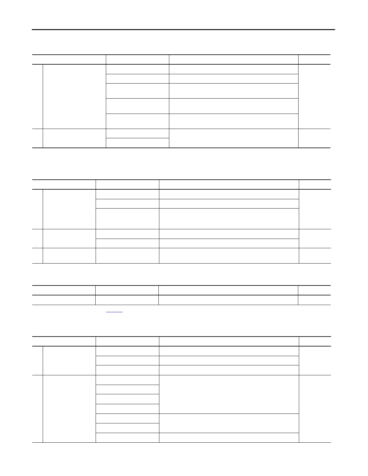
Table 23 - Test Output Parameters
Parameter Name
(1)
Value Description Default
x Test Output Mode Not Used An external device is not connected. Not Used
Standard The output is connected to a standard device.
Pulse Test A contact output device is connected. Use in combination with a safety
input.
Power Supply The power supply of a Safety Sensor is connected. The voltage that is
supplied to I/O power (V, G) is output from the test output terminal.
Muting Lamp Output (Terminal T1
or T3 only)
An indicator is connected and turned ON to detect broken lines in an
external indicator.
Test Output Fault Action Clear OFF Action to perform when a communication error is detected. Clear OFF
Hold Last Data
(1) Parameters that are directly related to safety are marked with an x in the left column.
Table 24 - Safety Digital Output Parameters
Parameter Name
(1)
Value Description Default
x Output Point Mode Not Used An external output device is not connected. Not Used
Safety When the output is ON, the test pulse is not output (remains ON).
Safety Pulse Test With use of this function, short-circuits between output signal lines and the
power supply (positive side) and short-circuits between output signal lines can be
detected.
x Output Point Operation Type Single Channel Use as single channel. Dual-channel
Dual-channel Use as dual-channel. When both channels are normal, outputs can be turned ON.
x Safety Output Error Latch
Time
0…65,530 ms
(in increments of 10 ms)
Safety output errors are latched for this time. 1000 ms
(1) Parameters that are directly related to safety are marked with an x in the left column.
Parameter Name Value Description Default
Test Output Idle State
(1)
Clear OFF or Keep Output Data Definition of output data is in idle state. Clear OFF
(1) Set only through Explicit Messaging. See for Appendix B more information.
Table 25 - Safety Analog Input Parameters
Parameter Name
(1)
Value Description Default
x Input Point Mode Not Used External input device is not connected.
Not UsedSafety A solid-state safety sensor is connected.
Standard A device that is not used in the safety loop is connected.
Range ±10V
Input voltage range.
4…20 mA
0…5V
0…10V
±5V
4…20 mA
Input current range.
0…20 mA
Tachometer Tachometer mode.
 Loading...


