114 Rockwell Automation Publication 2100-IN012G-EN-P - August 2016
Appendix A Bulletin 140G Unit Assembly Instructions
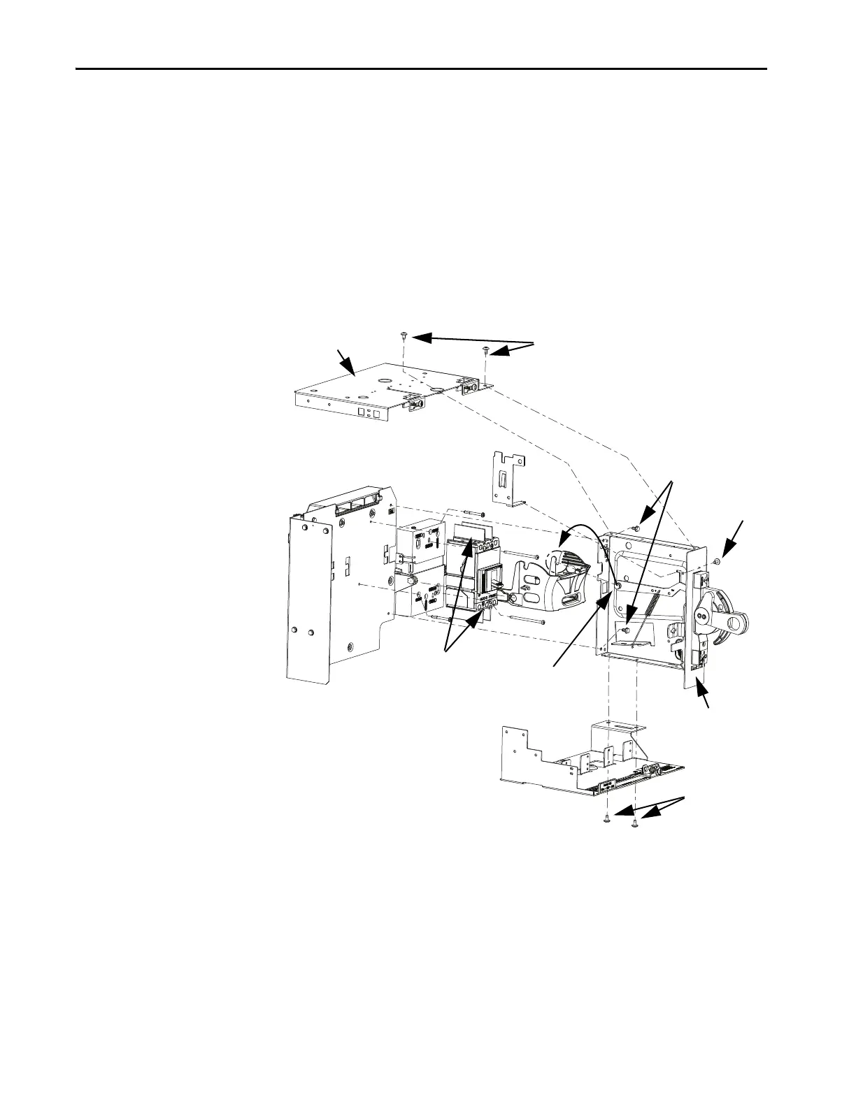
3. Remove the top plate and handle assembly.
a. Remove the unit interlock screw (5/16 in.), press the tabs together,
and remove the unit interlock.
b. To remove the top plate, remove the top plate screws.
c. Optional - remove handle assembly from the right side.
There are two screws on bottom and two screws on the inside top
and bottom (5/16 in.).
d. Remove the linkage from the bale.
4. Disconnect the circuit breaker wiring.
a. Remove terminal cover mounting screw and slide the terminal cover
forward (click when pulling).
b. To remove the line side connection (top wires) use an allen wrench
(G and H-frame 5 mm hex, J-frame 6 mm).
Make note of the phasing of the cables.
c. To remove the load side connection (bottom wires) use an allen
wrench (G and H-frame 5 mm hex, J-frame 6 mm).
TIP For SecureConnect™ units, cut wire tie and to remove wires.
Unit Interlock
Unit Interlock
Screw
Top Plate
Handle
Assembly
Linkage
Bale
Top Plate Screws
Handle
Assembly
Screws
Handle
Assembly
Screws
Circuit
Breaker
Wiring
Terminals

 Loading...


