Rockwell Automation Publication 2100-IN012G-EN-P - August 2016 115
Bulletin 140G Unit Assembly Instructions Appendix A
5. Place the circuit breaker in the ON position.
Use a large slotted screwdriver (we recommend a 3/8 or 1/2 in. wide
blade) to remove the bale.
6. To remove the bale, on the left side of the bale, place the screwdriver flat
on the side and rotate the screwdriver.
7. To remove the circuit breaker, remove two Phillips screws.
Save the lock washers and screws.
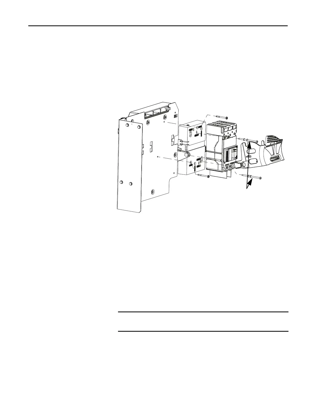
Install Circuit Breaker
To install the Bulletin 140G circuit breaker in a vertical handle unit, follow
these steps.
1. Attach the handle assembly to the mounting plate by using #10-32 x
0.38 thread-forming screws and tighten to 20…40 lb•in
(2.25…4.50 N•m).
2. If optional external auxiliary contacts are used, attach the external
auxiliary bracket (not included in the kit) to the circuit breaker base.
3. Position the base on the mounting plate.
Use the vertical mounting holes (2100V).
4. Mount the base to the mounting plate by using #8-32 x 1.62 Pan head
screws (G frame units); #8-32 x 0.81 Pan head screws (H and J frame
units).
Bale
Circuit
Breaker
Phillips
Screws and
Lock Washers
IMPORTANT Keep the base flat during assembly; do not support it on the side.
Keep the left screw on the bracket base loose to adjust the bracket later.

 Loading...


