Rockwell Automation Publication 2100-IN012G-EN-P - August 2016 39
Installation Procedures Chapter 2
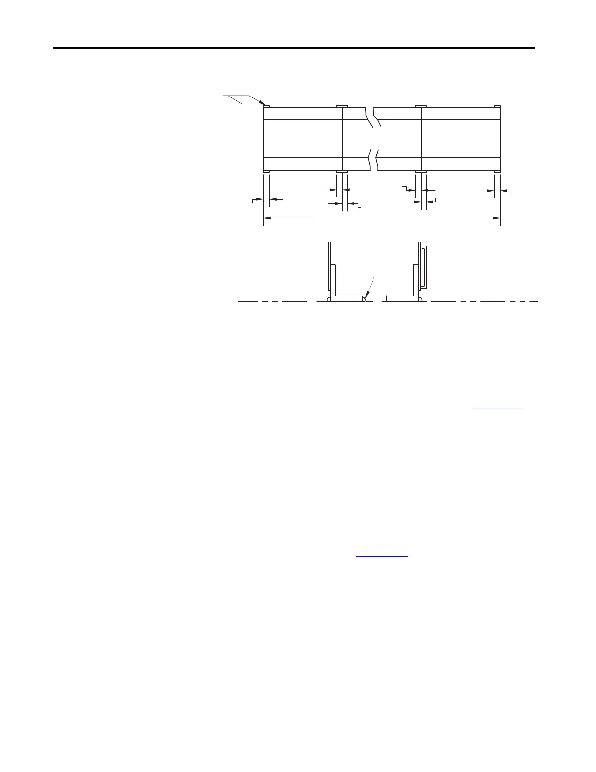
Figure 23 - Seismic Weld Down Requirements
Joining and Splicing New
MCCs
A main horizontal bus splice kit must be installed between shipping blocks of
new MCCs to connect the main horizontal bus. In addition, the neutral bus
splice kit (if required) and the ground bus splice kit must be installed between
shipping blocks. Refer to CENTERLINE 2100 Motor Control Centers
Joining and Splicing Vertical Sections Instructions, publication 2100-IN010
.
Joining and Splicing Existing
MCCs
A main horizontal bus, a neutral bus (if required), and a ground bus splice kit
must be installed when adding to existing CENTERLINE MCCs. When
adding to existing MCCs, you must identify the series of the MCC that you are
adding to. If the existing MCC is series A or B, you must consult MCC
technical support at 1.440.646.5800 and follow the prompts to Allen-Bradley
> Low Voltage Motor Control Centers > Post Shipment Support for joining
and splicing procedures. When the existing MCC is series C or later, refer to
CENTERLINE 2100 Motor Control Centers Joining and Splicing Vertical
Sections Instructions, publication 2100-IN010
.
Also, be sure to connect network cables and other control cables as required.
0.25 in. (6 mm)
1.50 in. (38 mm)
1.50 in.
(38 mm)
1.50 in. (38 mm)
1.50 in. (38 mm)
1.50 in. (38 mm)
1.50 in.
(38 mm)
Rear
Front
First Section Last Section
Second Section and
Additional Sections
MCC Lineup
Rear
Front
Optional Location
for Rear Welds
Floor Line
Left-hand Side View